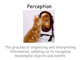
Perception
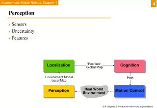
4. Perception. Sensors Uncertainty Features. "Position". Localization. Cognition. Global Map. Environment Model. Path. Local Map. Real World. Perception. Motion Control. Environment. 4.1. Example HelpMate, Transition Research Corp. 4.1. Example B21, Real World Interface. 4.1.

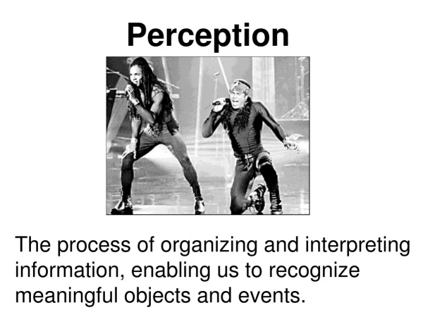
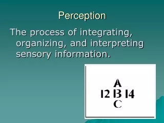
Perception
E N D
Presentation Transcript
4 Perception • Sensors • Uncertainty • Features "Position" Localization Cognition Global Map Environment Model Path Local Map Real World Perception Motion Control Environment
4.1 Example HelpMate, Transition Research Corp.
4.1 Example B21, Real World Interface
4.1 Example Robart II, H.R. Everett
4.1 Savannah, River Site Nuclear Surveillance Robot
4.1 BibaBot, BlueBotics SA, Switzerland Omnidirectional Camera Pan-Tilt Camera IMUInertial Measurement Unit Sonar Sensors Emergency Stop Button Laser Range Scanner Wheel Encoders Bumper
Our new robot: Killianunder development top sonar ring stereo vision gripper with sensors: IR rangefinders strain gauge laptop brain laser range-finder bottom sonar ring
4.1.1 General Classification (Table 4.1)
4.1.1 General Classification (Table 4.1, cont.)
Sensor Terminology • Sensitivity • Dynamic Range • Resolution • Bandwidth • Linearity • Error • Accuracy • Precision • Systematic Errors • Random Errors
4.1.6 Active Ranging Sensors : Ultrasonic sensor 4.1.6 • transmit a packet of (ultrasonic) pressure waves • distance d of the echoing object can be calculated based on the propagation speed of sound c and the time of flight t. • The speed of sound c (340 m/s) in air is given by where : ration of specific heats R: gas constant T: temperature in degree Kelvin
4.1.6 Ultrasonic Sensor (time of flight, sound) Wave packet Transmitted sound Analog echo signal Threshold Digital echo signal Integrated time Output signal threshold integrator Time of flight (sensor output) Effective range: typically 12 cm to 5 m
4.1.6 Ultrasonic Sensor (time of flight, sound) • typically a frequency: 40 - 180 kHz • generation of sound wave: piezo transducer • transmitter and receiver separated or not separated • sound beam propagates in a cone like manner • opening angles around 20 to 40 degrees • regions of constant depth • segments of an arc (sphere for 3D) Typical intensity distribution of a ultrasonic sensor
SRF10 sensor • Range: 3 cm to 6 m • See also www.acroname.com
4.1.6 Ultrasonic Sensor Problems • Soft surfaces that absorb most of the sound energy • Undesired from non-perpendicular surfaces • Specular reflection • Foreshortening • Cross-talk between sensors • What if the robot is moving or the sensor is moving (on a servo motor)? • What if another robot with the same sensor is nearby?
4.1.6 Optical Triangulation (1D) D Principle of 1D triangulation. • distance is proportional to 1/x Laser / Collimated beam P Target L Transmitted Beam x Reflected Beam Lens Position-Sensitive Device (PSD) or Linear Camera http://www.acroname.com/robotics/parts/SharpGP2D12-15.pdf
IR Sensor (aka Top Hat sensor) Used for: Line following Barcode reader Encoder
4.1.5 Ground-Based Active and Passive Beacons • Elegant way to solve the localization problem in mobile robotics • Beacons are signaling guiding devices with a precisely known position • Beacon base navigation is used since the humans started to travel • Natural beacons (landmarks) like stars, mountains or the sun • Artificial beacons like lighthouses • The recently introduced Global Positioning System (GPS) revolutionized modern navigation technology • Already one of the key sensors for outdoor mobile robotics • For indoor robots GPS is not applicable, • Major drawback with the use of beacons in indoor: • Beacons require changes in the environment -> costly. • Limit flexibility and adaptability to changing environments.
4.1.5 Global Positioning System (GPS) • Developed for military use • Recently it became accessible for commercial applications • 24 satellites (including three spares) orbiting the earth every 12 hours at a height of 20.190 km. • Four satellites are located in each of six planes inclined 55 degrees with respect to the plane of the earth’s equators • Location of any GPS receiver is determined through a time of flight measurement • Technical challenges: • Time synchronization between the individual satellites and the GPS receiver • Real time update of the exact location of the satellites • Precise measurement of the time of flight • Interferences with other signals
4.1.5 Global Positioning System (GPS) 4 satellites provide (x,y,z) and time correction Satellites synchronize transmissions of location & current time GPS receiver is passive
4.1.6 Laser Range Sensor (time of flight, electromagnetic) (1) • Transmitted and received beams coaxial • Transmitter illuminates a target with a collimated beam • Receiver detects the time needed for round-trip • A mechanical mechanism with a mirror sweeps • 2 or 3D measurement
4.1.6 Laser Range Sensor (time of flight, electromagnetic) (2) Time of flight measurement • Pulsed laser • measurement of elapsed time directly • resolving picoseconds • Beat frequency between a frequency modulated continuous wave and its received reflection • Phase shift measurement to produce range estimation • technically easier than the above two methods.
4.1.6 Laser Range Sensor (time of flight, electromagnetic) (3) • Phase-Shift Measurement Wherec: is the speed of light; f is the modulating frequency; D’ is the total distancecovered by the emitted light • for f = 5 Mhz (as in the A.T&T. sensor), l = 60 meters l = c/f
4.1.6 Laser Range Sensor (time of flight, electromagnetic) (4) • Distance D, between the beam splitter and the target • where • : phase difference between the transmitted and reflected light beams • Theoretically ambiguous range estimates • since for example if = 60 meters, a target at a range of 5 meters = target at 65 meters (2.33)
4.1.6 Laser Range Sensor (time of flight, electromagnetic) (5) • Confidence in the range (phase estimate) is inversely proportional to the square of the received signal amplitude. • Hence dark, distant objects will not produce such good range estimated as closer brighter objects …
4.1.6 Laser Range Sensor (time of flight, electromagnetic) • Typical range image of a 2D laser range sensor with a rotating mirror. The length of the lines through the measurement points indicate the uncertainties.
4.1.8 Vision-based Sensors: Sensing • Visual Range Sensors • Depth from focus • Stereo vision • Motion and Optical Flow • Color Tracking Sensors
4.1.8 Vision-based Sensors: Hardware • CCD (light-sensitive, discharging capacitors of 5 to 25 micron) • CMOS (Complementary Metal Oxide Semiconductor technology)
4.1.8 Color Tracking Sensors • Motion estimation of ball and robot for soccer playing using color tracking
Cyan = (0,255,255) Magenta = (255,0,255) White = (255,255,255) Yellow = (255,255,0) Image representation (1,1) (640,480) B = (0,0,255) G = (0,255,0) R = (255,0,0)
Image Representation YCrCb illumination data stored in a separate channel (may be more resistant to illumination changes) R-G-B channels map to Cr-Y-Cb where Y = 0.59G + 0.31R + 0.11B (illumination) Cr = R-Y Cb = B-Y
CMU cam • Ubicom SX28 microcontroller with 136 byes SRAM • 8-bit RGB or YCrCb • Max resolution: 352 x 288 pixels • Resolution is limited to 80 horizontal pixels x 143 vertical pixels because of the line by every other line processing. (1,1) (352,288) (80,143)
CMU cam Operation • init_camera() • auto-gain – adjusts the brightness level of the image • white balance adjusts the gains of the color channels to accommodate for non-pure white ambient light • clamp_camera_yuv() • point the camera at a white surface under your typical lighting conditions and wait about 15 seconds • trackRaw(rmin, rmax, gmin, gmax, bmin, bmax) • GUI interface for capturing images and checking colors
CMU cam Tracking • Global variables • track_size … in pixels • track_x • track_y • track_area … area of the bounding box • track_confidence (1,1) (80,143)
CMU cam – Better tracking • Auto-gain • Adjusts the brightness level of the image • White balance • Adjusts the color gains on a frame by frame basis • Aims for an average color of gray • Works great until a solid color fills the image • One strategy – use CrYCb • Aim at the desired target and look at a dumped frame (in GUI) • Set the Cr and Cb bounds from the frame dump • Set a very relaxed Y (illumination)
4.1.8 Adaptive Human-Motion Tracking