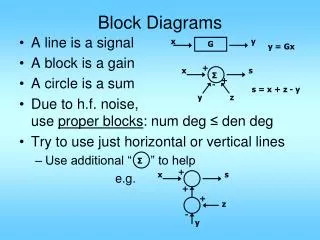
Reliability Block Diagrams
Reliability Block Diagrams. A reliability block diagram is a success-oriented network describing the function of the system. If the system has more than one function , each function is considered individually, and separate reliability block diagram is established for each system function.

Reliability Block Diagrams
E N D
Presentation Transcript
Reliability Block Diagrams • A reliability block diagram is a success-oriented network describing the function of the system. • If the system has more than one function, each function is considered individually, and separate reliability block diagram is established for each system function. • Each component is illustrated by a block. When there is a connection between the end points, we say that component i is functioning.
Example Consider apipeline with two independent safety valves that are physically installed in series. These valves are supplied with a spring-loaded, fail-safe, close by hydraulic actuator. The valves are opened and held open by hydraulic control pressure and is closed automatically by spring force whenever the control pressure is removed or lost. In normal operation both valves are held open. The main function of the valves is to act as a safety barrier, i.e., to close and stop the flow in the pipeline in case of an emergency.
Example It is usually an easy task to convert a fault tree to a reliability block diagram. In this conversion, we start from the top event and replace the gate successfully. An OR-gate is replaced by a series structure of the “components” directly beneath the gate, and an AND-gate is replaced by a parallel structure of the “components” directly beneath the gate.
Structure Function The state of component i can be described by a binary state variable, i.e., Similarly the state of a system can be described by a binary function
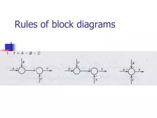
Series and Parallel Structures • Series • Parallel
Coherent Structures Definition:A system is said to be coherent if all its components are relevant and the structure function is non-decreasing in each argument. Relevant: Irrelevant: Non-decreasing structure function:
Example • Component 2 is irrelevant 1 2 a b 1
Redundancy at Component Level We obtain a better system by introducing redundancy at component level than by introducing redundancy at system level.
Path Sets and Cut Sets • A structure of order n consists of n components numbered from 1 to n. The set of all components is denoted by C. • A path setP is a set of components in C which by functioning ensures that the system is functioning. A path set is said to be minimal if it cannot be reduced without loosing its status as a path set. • A cut setK is a set of components in C which by failing causes that the system to fail. A cut set is said to be minimal if it cannot be reduced without loosing its status as a cut set.
Critical Path A critical path vector for component i is a state vector Such that A critical path set corresponding to the critical path vector for component i is defined by
Example Consider 2-out-of-3 structure
Structure of Composed Components Partition into subsystems is done in such a way that each component never appears within more than one of the subsystems.
Coherent Modules Let the coherent structure be given, and let Then is said to be a coherent module of if can be written as a function where is the structure function of a coherent system. What we actually do here is to consider all the components with the index belonging to A as one “component” with state variable . When we interpret the system in this way, the structure function can be written as
Modular Decomposition A modular decomposition of a coherent structure is a set of disjoint modules together with an organizing structure such that
Prime Module A module that cannot be partitioned into smaller modules without letting each component represent a module, is called a prime module. III represents a prime module. II is not since it may be described in Fig 3.35 and hence can be partitioned into IIa and IIb.