Download
1 / 13
130 likes | 282 Vues
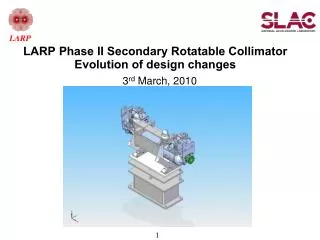
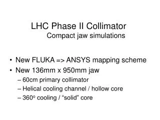
LHC Phase II Collimator Compact jaw simulations. New FLUKA => ANSYS mapping scheme New 136mm x 950mm jaw 60cm primary collimator Helical cooling channel / hollow core 360 o cooling / “solid” core. Mapping FLUKA => ANSYS Original Scheme.

E N D
LHC Phase II CollimatorCompact jaw simulations • New FLUKA => ANSYS mapping scheme • New 136mm x 950mm jaw • 60cm primary collimator • Helical cooling channel / hollow core • 360o cooling / “solid” core
Mapping FLUKA => ANSYSOriginal Scheme • 10x10x24 FLUKA bins mapped to ANSYS elements, one for one • Energy density of FLUKA bin applied to ANSYS element • Outer row of ANSYS mesh sized equal to FLUKA • On average, less volume in ANSYS model, therefore less tot energy • Bins with poorest match contain least energy
Mapping FLUKA => ANSYSnew scheme & comparison ANSYS nodes located within FLUKA bin are assigned energy density of that bin
Mapping FLUKA => ANSYSnew & old schemes compared • Peak temperatures generally slightly lower • Net energy deposit ~ same (previous slide) • Deflection up to 16% lower • due to different energy distribution (?) • Both models sufficiently accurate for engineering purposes
Conceptual design - coolant channels beam water Limited cooling arc: free wheeling distributor – orientation controlled by gravity – directs flow to beam-side axial channels. Pro: Far side not cooled, reducing DT and thermal distortion. Con: peak temperature higher; no positive control over flow distributor (could jam); difficult fabrication. 360o cooling by means of helical (or axial) channels. Pro: Lowers peak temperatures. Con: by cooling back side of jaw, increases net DT through the jaw, and therefore thermal distortion; axial flow wastes cooling capacity on back side of jaw.
Helical cooling passages – fabrication concept Preferred design due to fabrication ease, minimal weld or braze between water & vacuum • Tube formed as helix, slightly smaller O.D. than jaw I.D. • O.D. of helix wrapped with braze metal shim • Helix inserted into bore, two ends twisted wrt each other to expand, ensure contact • Fixture (not shown) holds twist during heat cycle Variations: • Pitch varies with length to concentrate cooling • Two parallel helixes to double flow • Spacer between coils adds thermal mass, strength • Fabricate by electroforming on helix
New “Compact” Jaw • Original jaw: 150mm diam x 1.2m long • Won’t fit available space - limited by beam spacing • New jaw: 136mm diam x .95m long , including 10cm tapered ends • Tank 72mm wider & 22mm deeper • 45mm max aperture
Simulations – Evolution of ANSYS model Water cooled 136mm x 25mm wall x1200mm long 136mm x1200mm long 3-d model FLUKA generated energy deposit mapped to blue area Water cooling: assume sufficient water that temperature is constant 360o complete I.D. cooled ~45o between arrows cooled => less distortion 2-d model 25 x 80mm grid FLUKA generated energy deposit at shower max “Solid” model Solid core => less distortion Cooling channel: ~45o arc between arrows (modeling expedient) Cooling applied to OD only of slot
Evolution of ANSYS models 136mm x 950mm long 136mm x 950mm long 2x 5mm sq channels 53o cooling arc Compact geometry OD and length reduced to fit space constraints Water cooling: Various arc lengths modeled assume sufficient water that temperature remains constant Tubular cooling channels More realistic modeling of heat path Water cooling: Circumference of square tubes cooled – area equal to 53o arc 5mm sq tubes equivalent cross section to 6mm diameter Assume sufficient water that temperature remains constant
Evolution of ANSYS Models 136 OD x 71 ID x 950 L beam Uniform ID Cooling Approximates effect of helical or axial flow Water cooling: assume sufficient water that temperature remains constant H2O simulation – helical flow shown Fluid pipe elements: Water temperature responds to heat absorbed from jaw More realistic simulation Axial pipes can simulate axial flow Friction can be simulated
Compact (136x950) jaw variations - performance comparison 1 2 3 4 5 6 7 8 9
Compact (136x950) jaw variations – compare simulation models
Compact (136x950) jaw variations – compare design concepts • Preferred: helical flow concept • Pro • less water-vacuum weld/braze • Con • Excessive deflection – 280um SS • Secondary: beam side only axial flow concept • Pro • Less deflection – 63um SS • Con • More water/vacuum weld/braze • Mechanically risky flow distributor