Download

1 / 29
290 likes | 446 Vues
Trapped Mode Analysis of the SLAC Rotatable Collimator Design for the LHC Phase II Upgrade. Liling Xiao Present at CREN LHC Collimation Working Group Meeting March 1, 2010. 1. OUTLINE. Original Collimator Design for the LHC Operation - Longitudinal Trapped Mode Calculations

E N D
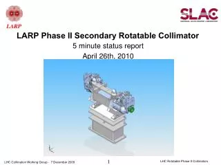
Trapped Mode Analysis of the SLAC Rotatable Collimator Design for the LHC Phase II Upgrade Liling Xiao Present at CREN LHC Collimation Working Group Meeting March 1, 2010 1
OUTLINE • Original Collimator Design for the LHC Operation - Longitudinal Trapped Mode Calculations - Transverse Trapped Mode Calculations - Heating Analysis • Current Collimator Design for the SPS Testing - Longitudinal Trapped Mode Calculations - Transverse Trapped Mode Calculations - Heating Analysis • Summary L. Xiao, Feb.12, 2010 2
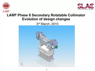
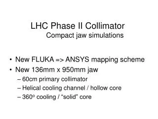
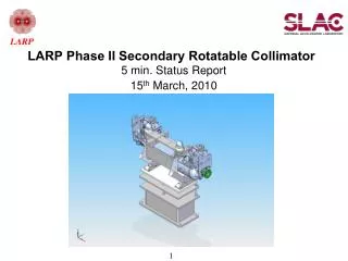
SLAC Rotatable Collimator LHC Operation SPS Testing Current design Jaw’s opening = 2mm / 60mm Original design Jaw’s opening = 2mm / 42mm Courtesy Steven Lundgren Vacuum tank is made of stainless steel (sigma=0.116e7s/m); jaws and EM foils are made of copper (sigma=5.8e7s/m) L. Xiao, March 1, 2010 3
Rotatable Jaw Original design Current design EM foils • There are 20 facet faces on each cylindrical jaw surface. • The two jaws can be rotated. • The two jaws will move in and out during operation. L. Xiao, March 1, 2010 4
Trapped Mode Excitation in Collimator Ez Longitudinal Modes When the beam passes through the collimator, the longitudinal modes with Ez component on z beam axis can be excited resulting in energy loss and collimator power dissipation. Transverse Modes When the beam crosses the collimator at an y-offset, the transverse modes with Ey component between the two jaws are excited generating a transverse kick in the y-direction as well as couple-bunch instability. Ey L. Xiao, March 1, 2010 5
Original Models – LHC Operation R_beampipe=42mm, Fc=2.1GHz Jaw’s opening=2mm / 42mm Rectangular Tank Circular Tank Partial Circular Tank L. Xiao, March 1, 2010 6
Eigensolver Omega3P Mode Calculation with Omega3P • Tetrahedras with 2nd order curved surface • Denser mesh along beam path plus 3rd order basis functions y x Finite Element Mesh L. Xiao, March 1, 2010 7
Longitudinal Modes – LHC fully inserted jaws, jaw gap=2mm The longitudinal modes have similar R/Qs in the three vacuum chamber designs, but have higher Qs in the circular design and lower Qs in the rectangular design. L. Xiao, March 1, 2010 8
Lowest Longitudinal Modes - LHC Jawgap=2mm E-field B-field f1=80MHz, Q=258. The trapped mode locates between the jaw and chamber wall. It is TEM-like mode and Q is the lowest. f1=103MHz, Q=2340. The trapped mode spreads around the jaw. It is cavity like mode. Q is the highest. f1=97MHz, Q=648. The trapped mode locates between the jaw and support plate as well as spreads around the jaw. Q is moderate. The longitudinal modes in the circular vacuum chamber are cavity like modes and have more fields spreading around the jaws. L. Xiao, March 1, 2010
Two Jaw Gaps – Longitudinal Modes Partial Circular Tank The longitudinal modes have higher R/Q for fully retracted jaws than for fully inserted jaws. L. Xiao, March 1, 2010 10
Lowest Longitudinal Modes E-fields Gap=2mm, F=97.2MHz, R/Q=1.28e-4ohm/collimator Gap=42mm, F=92.7MHz, R/Q=2.97e-2ohm/collimator 0.01 0.1 The longitudinal modes exist in the transition regions. There are more Ez fields in the transition regions along the beam path when the jaws are fully retracted. L. Xiao, March 1, 2010 11
Two Jaw Gaps – Transverse Modes Rectangular Tank ~e5 The transverse modes have higher R/Q_T for fully inserted jaws than for fully retracted jaws in rectangular tank vacuum chamber design. It should be true for the partial circular vacuum chamber design. L. Xiao, March 1, 2010 12
Lowest Transverse Modes E-fields Gap=2mm, F=84.2MHz, R/Q_T=8.20e5ohm/collimator Gap=42mm, F=97.5MHz, R/Q_T=4.90e2ohm/collimator Gap=2mm Gap=42mm yoffset@ 0.5mm yoffset@ 0.5mm 11 150 Due to the small gap of the jaws, the Ey component is very strong over the full length of the collimator for the fully inserted jaws. L. Xiao, March 1, 2010 13
Original Design • The longitudinal modes have higher Qs in the circular vacuum chamber design, and lower Qs in the rectangular vacuum chamber design. • When the two jaws are fully retracted, there are more Ez components generated in the transition regions along the beam path. Max.R/Q_z ~ 3e-2 ohm/collimator • When the two jaws are fully inserted, there are stronger Ey components generated over the full length of the collimator. Max. R/Q_T ~ 8.2e+5 ohm/collimator L. Xiao, March 1, 2010 14
Resonant Heating from Trapped Modes Resonant power losses are due to the excitation of these trapped modes. Assuming all bunches are in phase with them and mode decay is lower from bunch to bunch (Td>>Tb): L. Xiao 15
Current Model – SPS Testing Courtesy Steven Lundgren R_beampipe=30.5mm Jaw’s opening=2mm / 60mm L. Xiao, March 1, 2010 16
Current / Original Models Courtesy Steven Lundgren Previous Design Current Design L. Xiao, March 1, 2010 17
Longitudinal Modes fully inserted jaws, jaw gap=2mm The longitudinal modes have higher R/Qs in the current design than in the original design. L. Xiao, March 1, 2010 18
Lowest Longitudinal Modes fully inserted jaws, jaw gap=2mm SPS LHC E-fields F=97.2MHz, R/Q=1.28e-4ohm/collimator F=87.4MHz, R/Q=2.10e-1ohm/collimator 0.01 0.17 LHC SPS In the current design, there are more Ez fields in the transition regions. L. Xiao, March 1, 2010 19
Lowest Transverse Modes fully inserted jaws, jaw gap=2mm LHC SPS LHC F=84.2MHz, R/Q_T=8.20e5ohm/collimator Nor. Ey SPS yoffset@ 0.5mm F=62.9MHz, R/Q_T=5.5e6ohm/collimator There are similar Ey components in the straight section in the current and original designs. L. Xiao, March 1, 2010 20
Two Jaw Gaps – Longitudinal Modes Current Design The longitudinal modes have similar R/Q for the fully inserted jaws and the fully retracted jaws in the current design for the SPS testing. L. Xiao, March 1, 2010 21
Lowest Longitudinal Modes E-field Gap=2mm: F=87.4MHz, R/Q=2.10e-1ohm/collimator Gap=60mm: F=73.6MHz, R/Q=3.65e-1ohm/collimator In the current design, the narrow EM foils can only perturb the Ez fields along the beam path without changing it significantly when the jaw gap varies. L. Xiao, March 1, 2010 22
Two Jaw Gaps – Transverse Modes Current Design The transverse modes have strong R/Q_T for fully inserted jaws than for fully retracted jaws.It is the same as the original design. L. Xiao, March 1, 2010 23
Lowest Transverse Modes E-field Gap=2mm, F=62.9MHz, R/Q_T=5.5e6ohm/collimator Gap=60mm, F=75.4MHz, R/Q_T=3.3e2ohm/collimator 150 6 yoffset@ 0.5mm yoffset@ 0.5mm Gap=2mm Gap=60mm There are strong Ey fields between the two jaws for fully inserted jaws. L. Xiao, March 1, 2010 24
Current Design • The longitudinal modes have higher R/Qs for fully inserted jaws in the current design than in the original design. • The transverse modes in the current design don’t change significantly with new transition parts. • Unlike the original design, the longitudinal modes have similar R/Qs for the fully inserted jaws and for the fully retracted jaws. Max.R/Q < 3.6e-1 ohm/collimator • Like the original design, the transverse modes have higher R/Qs for the fully inserted jaws than for the fully retracted jaws. Max. R/Q_T ~ 5.5e+6 ohm/collimator L. Xiao, March 1, 2010 25
Resonant Heating from Trapped Modes <2GHz I=0.582A I=0.23A I=0.582A L. Xiao, Feb.12, 2010 26/30
Transition Part VS. R/Q fully inserted jaws fully retracted jaws Modified current design Increasing the height of the EM foils can reduce the lower longitudinal modes R/Q effectively, thus reduce the beam heating. L. Xiao, March 1, 2010 27
Discussion • What is the impedance budget? What are the trapped mode parameters in the CERN collimator design? • Modifying the transition part can reduce the longitudinal modes R/Q_z. However, it can’t change the lowest transverse mode R/Q_T. • If the lowest transverse mode will cause a problem, we will put more efforts to reduce the lowest transverse mode R/Q_T by modifying the collimator geometry and Qext by adding the ferrite files in the collimator. L. Xiao, March 1, 2010 28
Summary • All trapped modes below 2GHz in the SLAC original and current rotatable collimator designs are calculated using Omega3P, and their RF heating effects are evaluated. • The longitudinal trapped modes in the cylinder vacuum chamber design have higher Q-value. • The longitudinal trapped modes in the current collimator jaw design have higher R/Q than in the original collimator jaw design. • Modified the transition part between the jaws and the vacuum chamber tank can reduce the longitudinal modes R/Q, thus reduce the beam energy loss and heating. • The heating due to the transverse trapped modes is negligible, but the transverse kick on the beam needs to be evaluated for fully inserted jaws. Special thanks to Fritz Caspers for his helpful discussions and advice. L. Xiao, March 1, 2010 29