Download
1 / 21
230 likes | 440 Vues
Simulating the Response of Fibrous Scaffolds for Tissue Engineering. Peter M. Anderson Department of Materials Science and Engineering The Ohio State University Collaborators: Harshad Paranjape, Yanyi Zhu, Gregory Ebersole Heather Powell, Jianjun Guan, Gunjan Agarwal, Samir Ghadiali

E N D
Simulating the Response ofFibrous Scaffolds for Tissue Engineering Peter M. Anderson Department of Materials Science and Engineering The Ohio State University Collaborators: Harshad Paranjape, Yanyi Zhu, Gregory Ebersole Heather Powell, Jianjun Guan, Gunjan Agarwal, Samir Ghadiali The Ohio State University Support: OSU Institute for Materials ResearchMultidisciplinary Team Building Grant
Outline • Motivation • Background • Experiment-Simulation Approach • Experimental input • fiber geometry in scaffolds • macro mechanical response • Output • Electrospun Fiber Properties • Vision and Challenges • Conclusions cyclic excitation Cell-matrix interaction
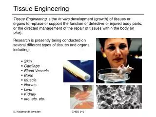
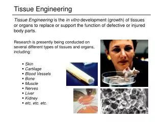
Motivation • Engineered Skin • 4 week waiting period • skin biopsy (1 wk) • fibroblasts (1 wk) • culture in scaffold (2 wk) • Outcomes: Engineered skin is • weak • too compliant • prone to tearing • lacks pigment, hair, nerves • Reduce time, improve properties Burn patient, post-op day 28 CourtesyST Boyce ES, day 14 Skin, adult breast
Background: Engineered Skin • Properties: governed by epidermal differentiation • Role of scaffold environment? Histology during culture: 7 to 21 days Mechanical Properties Ebersole Anderson, Powell. J. Biomechanics. 2010.
Background: Mechanical Environment • Used cross-linking to increase • modulus, E, of collagen gel substrate • E directs stem cell differentiation 1 kPa—brain—neurogenic 10 kPa—muscle—myogenic 100 kPa—collagenous bone—osteogenic • Chemical and mechanical environmentcritical to cell differentiation Engler, Sweeney, Discher, Schwarzbauer. J. Musc. Neur. Interac. 2007
Background: Modeling • Network models • Affine vs. non-affine deformation • How inhomogeneous is actual deformation? • Sources of nonlinearity (strain stiffening) • fiber straightening (unbending) • fiber rotation (reorientation) • fiber cross-links, contacts • fiber constitutive properties (s-e) • Scaffold geometry • from images or artificially generated? Sander et al. IEEE Eng. Medic. Biol. 2009 Stein et al. Complexity. 2011 Wang et al. J Eng Mater Tech. 2000
Background: Single Fiber Testing • Single fiber testing • bridge mode: stretching (AFM) - bridge mode: bending (AFM) • Difficult procedure. Physiological loading? Carlisle et al. Acta Biomater. 2010 Yang et al. Acta Biomater. 2008
Strategy • Get fiber s-e properties viaan experiment-modeling approach Exp. input: scaffold geometry Output: fiber s-e properties Finite Element Model Exp. input: Scaffold S-E response
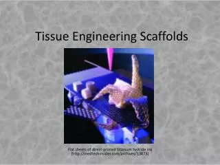
Background: Scaffold Synthesis • Material • 10% wt/vol solution of acid-soluble collagen type I • Fiber Spinning • 8.5 cm2 grounding plate • 30 kV potential, 20 cm distance, 4.5 ml/hr • Cross-linking • physical: vacuum dehydration, 140 C, 24 hrs • chemical: solution 5 mM 1-ethyl-3-3-dimethylaminopropylcarbodiimide hydrochloride in 100% ethanol
Experimental Input Before Hydratation • Scaffold fiber geometry • Confocal microscopy • hydrated in buffer • z-stack imaging • 5 mm slice x 150 slices per scaffold • Digitize coodinates->Finite Element Code • Extract Fourier spectra 100 um Hydrated Fourier amplitude/l 100 um Ebersole, Paranjape, Anderson, Powell. Acta Biomaterialia, in review.
Experimental Input • Macro Stress-Strain Response • Large "Toe" region (40% strain) Toe region
Finite Element Simulations • ABAQUS software • 54 fibers: beam elements • 20 x 20 x 5 mm system • 110% axial strain • imposed in X direction. • Negative transverse strain • Poisson effect Z Y X Before Deformation
Simulation Results • 110% axial strain along X-dir
FE Simulations: Fiber Properties • LE Fiber ModuliEf • Ef(small strain) = 0.35 MPa • Ef(large strain) = 1.11 MPa Simu Scaffold Simulations LE fibers Ef = 1.11MPa HyperE fiber s-e response Expe riments HyperE fibers LE FibersEf = 0.35MPa • Hyperelastic fiber model • nonlinear fiber s-e response Movie
Effect of System Size • Simulations of single fiber extension: • use Fourier spectra • 200 mm fibers: • more compliant • Rationale • longer fibers: • incorporate longer wavelength modes Fiber load (normalized) Fiber strain (DL/L0) before stretching during stretching
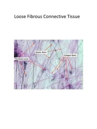
Variation in Fiber Response • Fiber stress vs. strain • Large statistical deviation • Cause? fiber geometry • Toe-in strain • from ~0 to >20% • Post Toe-in stiffness • uniform • Mean behavior • more rounded, gradual toe-in Collagen fibers, L = 200 mm Fiber stress (F/A0) 75 Fiber strain (DL/L0)
Challenges • Need larger model to encompass cell(s) • 200 x 200 x 50 microns • Cannot create by periodically replicating small 20 mm models • misses larger wavelengths • Confocal imaging • Conversion to fibercoordinates
Vision • Determine cell force footprints • after Legant et al. • polyethylene glycol hydrogels • lyse cells; measure resulting beaddisplacements (0.2 mm diam) • finite element model: deduce tractions • Results from Legant et al. • GFP expressing NIH 3T3 fibroblasts:0.1 – 5 kPa tractions • tractions as hydrogel modulus Legant et al. 2mm fluorescent beads tractions Legant et al. Nature Methods 7(12): 969 (2010).
Application to Fibrous Matrices • Confocal images at two states: (1) during cell differentiation/growth (2) after lysing • Get displacements u(i) at focal adhesion sites (i) btw states (1)-(2) • Construct FE mesh of state (2) • Determine focal adhesion forces f(i) needed to achieve measured u(i) • Green's functions: supplied by FE model.
Conclusions • Finite element (FE) modeling • input: fiber geometry; macro S-E behav. • output: local fiber properties • caveat: need large FE model to capturelarge wavelength contributions. • Long-range vision • capture cell force footprints, correlate with directed cell differentiation • Challenges • large scale images/automated import to FE • simulation times, esp. w/nonlinear system • stress-free state? • ex: local s-e properties type I collagen
Abstract Abstract The use of scaffolds for tissue engineering involves aspects of mechanotransduction that are controlled by scaffold properties and structure at the local, cellular scale. For fibrous, electrospun scaffolds, such features include the local fiber stress-strain behavior, fiber density, and undulations in fiber orientation. These serve to provide variations in local stiffness and anisotropy that cannot be quantified through macroscopic testing alone. A combined computational-experimental approach is adopted whereby finite element simulations of electrospun scaffolds are used to link the macroscopic stress-strain response to underlying fiber geometry and fiber stress-strain response. These simulations capture the discrete fiber-straightening, reorientation, and fiber-fiber contact that occurs during scaffold deformation. They can also provide scaffold “Green’s functions” to quantify local response to concentrated forces exerted by cells, enabling extraction of “cellular force footprints” in principle. The present simulations are informed by actual fiber geometries from high-resolution confocal microscopy images and macroscopic stress-strain data. An output is the local fiber stress-strain response, which is notoriously difficult to obtain by direct experimental measurement. The calibrated simulations underscore the highly non-uniform (non-affine) and anisotropic nature of the deformation. They also reveal the scale-dependent nature of mechanical response. The talk concludes with challenges to simulation “scale-up” and other pertinent issues. This work is supported by a Multidisciplinary Team Grant, Institute for Materials Research, The Ohio State University.