Download

1 / 62
620 likes | 741 Vues
This project aims to develop a heat conduction apparatus that effectively demonstrates fundamental heat transfer concepts for students new to hands-on engineering. The apparatus focuses on safety, accuracy, mobility, precision, longevity, and ease of use. It will facilitate a clear understanding of thermal conductivity through the observation of energy flow between hot and cold regions, utilizing modular components, sturdy materials, and a simple assembly process. Key specifications include the use of thermocouples for temperature measurement and adaptable connections for heating and cooling.

E N D
Group Members John Durfee, Ryan Murphy, Fielding Confer Dan Unger, Katie Higgins, Robin Basalla
Purpose To design a heat conduction apparatus that can illustrate fundamental concepts of heat transfer to students new to hands-on engineering
Keywords To quickly outline the primary goals, follow SAMPLE • Safety- minimal risk of student injury • Accuracy- correct measurements of conductivity • Mobility- can be maneuvered in and out of lab • Precision- measurements are easily repeated • Longevity- robust materials and long life span • Ease of use- simple assembly, disassembly, & cleaning
Top Level Function Uninformed Student Informed Student Demonstrate Principle of Thermal Conductivity Hands-on Experience Partial Assembly Energy Thermal Energy Unknown k Known k
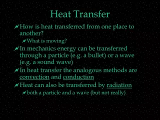
Fundamental Concept • A temperature gradient will be produced between a Hot and Cold regions • This gradient will be set across a span of Heat Conduction • The flow of energy will be allowed to reach steady state • The Energy In will be equivalent to the Energy Out • The temperature gradient will be measured with a transmission system Heat Conduction Cold Hot Temperature Transmission Energy In Energy Out
Benefits of Each System • Box-blocks • Modular pieces that are easily constructed • Box Clamp • Simple, rugged assembly • Broad range of Insulation can be used • Open for any type of specimen • Hinged • Minimal disturbance to transmitters
Putting It Together • Begin with a sturdy platform • Seat a solid block of bulk insulation • Include a second block formed to the specimen • Cover it with a malleable slab of insulation • Close everything with a second connected platform
Exploded View • Begin with a sturdy platform • Seat a solid block of bulk insulation • Include a second block formed to the specimen • Cover it with a malleable slab of insulation • Close everything with a second connected platform
Moving Forward • Considering previous decisions, i.e. • The Hot Side will use a cartridge heater • The Cold Side will use a liquid refrigeration unit • The Temperature Transmission will use thermocouples
Moving Forward • New subsystems needed to be identified • Heating Connection • Cooling Connection • Transmitter Connection
Moving Forward • The cartridge heater can be placed inside the specimen • The refrigerated fluid can cool the specimen with an external jacket • The thermocouples can be tacked to the specimen
Summarizing • Previous subsystems can be used to help categorize new elements • A new list of subsystems has to be generated
Categorized Subsystems • Hot Side • Heat Source • Heating Connection • Cold Side • Cold Source • Cooling Connection • Housing • Top • Bottom • Connection • Transmission • Transmitter Type • Transmitter Connection • Insulation • Upper • Middle • Lower Sections • Specimen • Geometry
Current Benefits • Modular design • Simple assembly • Rugged, easily replaceable components • Minimal stress on transmitter connections • Well insulated energy exchange
Current Issues • Need an appropriate method to tack thermocouples • No feasible material was found for the upper insulation (soft forming) • Unshielded insulation can be damaged • Housing connections need to be addressed
Thermocouple Connections • Options • High Temp Solder • Adhesive Patches • Thermal Epoxy • Drilled Holes
Thermocouple Connections • Pros • Solder • Accurate • Solid Connection • Adhesive Patches • Simple • Modular • Thermal Epoxy • Accurate • Drilled Holes • Accuracy • Modular • Cons • Solder • Dangerous • Messy • Adhesive Patches • Inaccurate • Thermal Epoxy • Time Intensive • Trades cost for accuracy • Messy • Drilled Holes • Permanent • Added Processing
Upper Insulation • Options • Rigid Formed (like middle) • Soft Fiberglass or alternative • Combined Structure
Upper Insulation • Pros • Rigid • Simple • Durable • Fiberglass • Cheap • Modular • Combination • Works best with ideas • Partially modular • Cons • Rigid • Needs processing • Less modular • Fiberglass • Less durable • Messy • Combination • More complicated • Needs processing
Housing • Insulation can be contained within a boxed housing • Did not require much decision making • Slots can be made for the thermocouple wires(as opposed to a long section) • Openings will also be needed on both the Hot and Cold Ends
Housing Connection • Options • Hand screws • Buckles • Structural Offset
Housing Connection • Pros • Hand Screws • Rugged • Solid Closure • Buckles • Simple Use • Solid Closure • Structural Offset • Simple • No Processing Needed • Less Expensive • Cons • Hand Screws • Needs processing • Can be over worked • Buckles • Needs processing • Less durable • Structural Offset • Less Solid Closure
Selections • Thermocouple Connections • Drilled Holes • Upper Insulation • Rigid and Formed • Housing • Box Enclosure • Housing Connection • Structural Offset
Still Need to Include • Hot Side • Energy Measurement (power source) • Cold Side • Coolant Carrier (tubing) • Cooling Fluid • Temperature Transmission • Data Collection Hardware • Data Collection Software • Housing • Construction (screws) • Used Specimen Container
Used Specimen Container • Holds each specimen after they have been heated and measured • Isolates heated material from students • Can be moved away from testing area • Uses the same material as the housing device
Final List of Subsystems • Hot Side • Energy Management • Heat Source • Heating Connection • Cold Side • Cold Source • Cooling Connection • Coolant • Tubing • Transmission • Transmitters • Connection • Data Collection Hardware • Data Collection Software • Specimen • Geometry • Insulation • Upper • Middle • Lower • Housing • Material • Connection • Fasteners • Used Container • Material • Insulation • Fasteners
Handout Bill of Materials
Characteristic Dimensions • Housing • (21x8x8)in box • 1in thick • Insulation • 6x(19x6x1)in • 2 milled sections • Specimen • 18in long • 1in diameter • Heater • 3/8in diameter • 1¼in length • Cooling Jacket • 1in diameter • 1.24in depth • Thermocouples • 5 total • Begin 3¼in down spec. • 3in apart
Cross Sections Hot Side Cold Side