Download
1 / 59
590 likes | 764 Vues
So Many Amplifiers To Choose From; Matching Amplifiers To Applications. Transfer Functions and Loop Gain Voltage Feedback, Current Feedback, FDA’s Loop Gain and other contributors to linearity Differential circuits and why. MFB Filter Design Transfer function with an ideal op amp

E N D
So Many Amplifiers To Choose From; Matching Amplifiers To Applications Transfer Functions and Loop Gain Voltage Feedback, Current Feedback, FDA’s Loop Gain and other contributors to linearity Differential circuits and why. MFB Filter Design Transfer function with an ideal op amp Design choices and recommendations Loop gain analysis and implications Example Designs Michael Steffes Market Development Manager High Speed Signal Conditioning
Loop Gain is Everything in Op Amps Op Amp suppliers are essentially selling a device that does impedance transformation (high input Z to low output Z) and a whole lot of open loop gain. The customer then closes the loop to get a more controlled voltage gain, but also gets a huge improvement in precision (both DC and AC) due to the high open loop gain. For high frequency parts, the DC open loop gain is a secondary issue and it is really the one pole rolloff curve that is of interest and where the magnitude of the open loop gain equals the inverse of the feedback ratio. (Loop Gain x-over).
Simplified FDA Analysis With the feedback ratios matched, this reduces to the same equation as an inverting VFB amplifier. Will have the same Loop gain Bode Plots. Considerable complexity in the analysis will result with imbalanced feedback ratios. Refer to TI app. Note SLOA054 for details. For this discussion, the FDA will be a subset of the VFB class of devices.
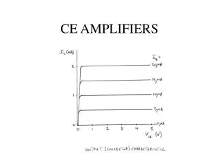
Comparing Voltage and Current Feedback Op Amps Two parts on the same process, at the same quiescent power, will have pretty similar open loop gain curves for VFB and CFB devices – Compare the OPA690 (VFB) and the OPA691(CFB) below. OPA690 Voltage Feedback (VFB) OPA691 Current Feedback (CFB) Dominant Pole at 80kHz Dominant Pole at 200kHz Gain of 2 (6dB) Loop Gain at 20Mhz is 14dB Gain of 2, Rf = 402ohms, Loop gain at 20Mhz is 16dB The loop gain profile is just slightly higher over frequency for the CFB version due to the higher dominant pole location
Theoretical Determinants of Harmonic Distortion An Ideal amplifier would take an input spectrum and pass it on to the output with the same gain for each Fourier component and no added power in the spectrum. We have not quite achieved that ideal, hence new amplifiers and techniques moving closer to this are still being introduced. Output spectral purity has many levels of consideration – the better you aspire to, the more of these levels you will have to consider. The first level is that, for a high open loop gain type of part, the output linearity will be the linearity intrinsic to the output stage corrected by the loop gain at the fundamental frequency. Low loop gain devices, like most RF amplifiers, achieve high linearity by making the signal power a very small part of the quiescent power. Hence you will see >80dBc SFDR type devices to very high frequencies using > 1.5W quiescent power
Distortion Analysis using Negative Feedbackwith Distortion modeled only as an Output Stage Distortion Distortion Differencing Signal Stage + Vd Vo + Vi Verr A + Forward Gain - f Feedback Ratio where Af ≡ Loop Gain. Output stage non-linearities are corrected by loop gain.
Paths to Improved Distortion Suggested by the Control Theory Model. OPA690, VFB, HD linear with log gain OPA691,CFB, HD more constant over gain At a first level, output linearity is the open loop distortion of the output stage, corrected by the loop gain. So, improving either of these will improve distortion. One key conclusion from the Loop Gain comparison between VFB and CFB is that the CFB holds a more constant loop gain over signal gain (Gain Bandwidth Independence). This should hold more constant distortion to higher gains than VFB.Comparing those plots for the VFB OPA690 and CFB OPA691 -
Continued Improvement in SFDR?? The 2nd Harmonic typically does not follow this theory exactly. There are other, external, effects that typically come into play on the even order terms for a single ended amplifier. Even order distortion can be visualized as ½ cycle imbalance on a sine wave. Odd order distortion can be visualized as curvature through zero on a sine wave. Anything that will take a purely balanced output sine wave and introduce perturbation on one ½ cycle but not the other, will be generating even order distortion terms. Suspects include – Mutual coupling in the negative supply pin to the non-inverting input Slightly imbalanced ground return currents getting into the input signal paths. Imbalanced supply decoupling impedance. One of the best ways to eliminate this issue is to run the signal path differentially – but exactly why does that work??
Why is it that a Differential Configuration Suppresses the 2nd harmonic??
Why is it that Differential configuration suppress the 2nd harmonic?? • Substituting in the two halves of differential input signal, getting to each output signal, then taking the difference - shows we are theoretically only left with the desired linear signal and the 3rd order term. Even if the A2 coefficient is not exactly matched between the two amplifiers, it is their difference that ends up being the gain for this 2nd order non-linearity at the output. We also see a reduction in the 3rd order coefficient - arising from only applying 1/2 of the input through each channel.
Single Ended Even order Terms become Odds in the Differential Configuration • In the time domain, this effect can be seen by producing a clipped waveform for the two outputs, then taking the difference. The individual outputs would have a very high even order harmonic content, while the differential signal will still be distorted, but will give rise to only odd harmonics since the clipping is now symmetric on each 1/2 cycle of the sinusoid.
Single Ended vs. Differential SFDR To illustrate the power of differential designs in suppressing HD2, the plots below show the HD2 and HD3 for a low noise, low distortion VFB dual amplifier in both single ended and differential configurations. The test conditions give the same loop gain, but the differential test had a 35ohm load to each output while the single ended was a 100ohm – which raised the HD3 quite a bit.
Key Elements to Understanding and Improving Distortion External conditions that will influence distortion Required Output Voltage and Current as a portion of the quiescent power and design of the output stage This is including loading and supply voltage effects as well. Adding a higher standing current in the output stage will often lower distortion with no effect on noise. This Class A current can pick up about 10dB on the 3rd. Loop gain – use a VFB designed for the desired gain setting or, at higher gains use a CFB device. Frequency – since loop gain changes with frequency, a fixed output stage non-linearity will give a changing distortion over frequency. Layout and Supply Decoupling This is covered in detail in TI – app. Note SBAA113
MFB Filter Design Transfer function with ideal Op amp Design choices and recommendations Loop gain analysis and implications Example Design with unity gain and non-unity gain VFB Devices Example Design with FDA Device Applying these Concepts to the MFB Filter
MFB (Multiple FeedBack) Low Pass Filter Can also call this an “Integrator Based Filter” because imbedded inside the filter is an integrator circuit (R2 and C2) which is of critical interest to the op amp for stability. Since it is an integrator op amp application, a couple of constraints come in Should be a unity gain stable voltage feedback op amp. We will overcome the unity gain stability constraint later but you cannot (easily) use a current feedback device in this filter. At DC, the signal gain is –R1/R3. Later, we will see that R3 only impacts the Q of the filter shape (not the wo). Tuning R3 for Q will, however, also be changing the DC Gain. Starting point for the MFB Filter Design
The MFB filter provides much better stopband rejection than an equivalent Sallen-Key filter (also called VCVS filter) The MFB filter is also much more forgiving of lower bandwidth op amps in terms of the close loop pole sensitivity to amplifier gain bandwidth product. At least for low Q designs, it gets much more sensitivity at higher Q In theory, it is impossible to make this circuit oscillate (at least with really slow op amps put into the circuit) What advantages does an MFB filter provide.
The plot below compares two designs for a Butterworth low pass design using an MFB and then a Sallen Key design using the same low speed amplifier Note the improved stopband rejection achieved for the MFB The Sallen Key filter eventually shows signal feedthrough to the output through the feedback capacitor that gives the rising portion of the output curve. (from sboa049b, Active Low Pass Filter Design, Jim Karki) Stop Band Rejection Comparison
The equations below show the transfer function – and the key design elements resulting from this. Ideal Transfer Function for the MFB Low Pass Filter
As is normally the case in active filter design, we have more components to resolve than filter design parameters. Here, there are 5 external elements to resolve from which we need to set 1. DC Gain (this will be just -R1/R3). Call this Av and only use the magnitude in the filter design (but we will get an inverting gain through the filter) 2. Filter wo (characteristic frequency in radians) 3. Filter Q (quality factor, unitless) We need to come up with 2 more constraints to uniquely resolve all 5 component values to get a nominal design for the filter. Another way to say this is that there is an infinite number of external component combinations that will give the desired filter shape. But the internal details of the filter performance vary significantly as different component combinations are selected. MFB Filter Design Methodology
In active filter design the other issues that can be used to constrain component values are noise and distortion. At low frequencies, before the capacitors come into play for this low pass filter, the noise of R2 adds directly to the voltage noise of the op amp to set the apparent input noise voltage for calculation purposes. It might not be too unreasonable to constrain R2 to add the same (or lower) output noise power as the op amp’s input noise voltage. The full expression for output noise at low frequencies is relatively complicated. But first, let’s look at the DC part of this circuit and set up for DC bias current cancellation using a resistor on the non-inverting input - Rp MFB Filter Design Methodology
MFB DC Analysis Circuit To improve the output DC precision, for bipolar input Op amps,
MFB Noise Analysis Circuit and Total Output Noise Equation Non-inverting input terms R1 and R3 noise R2 terms Inverting current noise term en is the op amp voltage noise in is the current noise – assumed equal for VFB op amps on each input This is not attempting to include any bandlimiting effects of the filter caps.
This complete equation includes a couple of terms that we can safely ignore. The Rp resistor is in place if bias current cancellation is part of the intended design. However, in the final circuit a large capacitor should be placed across this resistor to attenuate the noise contributions due to Rp. Recall that CMOS or FET input stages (or current feedback amplifiers in general) will not benefit from adding this Rp towards improving output DC accuracy. The en will come from the amplifier selected – so that is a fixed portion of the total output noise equation. R2 adds several terms that can, if you are not careful, dominate over the en term. So if a low noise amplifier was selected for its noise, setting R2 consistent with that will retain the original intent. R3 will also add noise in a similar fashion to R2 – it will turn out that setting R3≈ R2 is good for other reasons – so we will use that as a working assumption in setting an upper limit for R2 in this noise analysis Output Noise Analysis
Pulling the en term out and setting equal (in power) to the terms due to R2 and R3 – (neglecting the R1 terms as they will be set by R3 and the target gain) Approximate Target for a Maximum R2 Solving for R2 As an approximation, let R3 = R2, then using Solving this
With R2 selected from a noise control perspective, we can then proceed to picking C2 to put the integrator pole over a wide range of locations. Then, with 2 of the 5 passive elements selected, the target filter shape can be set with the remaining 3. It is best to look at the (1/R2C2) issue from a noise gain control standpoint. The following circuit is the feedback analysis circuit for the MFB filter where an added capacitor (CT) is included at the inverting node – this will be either a parasitic that needs to be included or a tuning capacitor for phase margin control. It has no direct impact on the desired filter transfer function but can impact loop gain & phase margin significantly. Setting the Integrator Pole
The following equation is the gain from Vo to V-. This is often called β in the control theory literature. The “noise gain” (1/β) is also given below. Noise Gain Transfer Function As is always the case, the poles of the noise gain are the same as the desired filter poles. It is useful to re-write this 1/βin terms of the target filter elements (letting CT = 0 to simplify)
Re-writing the Noise Gain (1/β) in terms of the desired filter design terms gives (where that equation is simplified by letting CT=0, for now) The poles are again the desired filter ωo and Q while the zeroes are also set by these terms plus an added (1/R2C2) in the linear term. Important points At DC (s=0), the noise gain is 1 + Av At s ∞, the noise gain becomes 1 + CT/C2 (from the previous full eq.) The 2 – zeroes and 2 poles control the transition between these two gains. The only added degree of freedom in setting the zeroes is the integrator pole location – everything else is already determined by the desired filter shape. It can be proven that the zeroes are always real – it is not possible to get complex zeroes in this equation. Setting the 1/R2C2 becomes the focus of the design from here. Noise Gain Transfer Function
Stepping through some algebra to get an isolated solution for C1, the following expression results that only leaves us to select C2 (if R2 is already chosen) The wo (R2C2) term is of some interest. This is the ratio of the target ωo to the embedded integrator pole. The equation above will only solve for a non-negative C1 if the term in the denominator is positive. This sets a limit to the maximum ratio of wo to the integrator pole. Moving the R2C2 term around (always satisfying the constraint implied by the above equation), will be changing the noise gain zeroes as shown on the previous slide which will then be changing the loop gain MFB Filter Design Methodology
It is a bit simpler to work with this ωo (R2C2) term inverted. That then becomes the ratio of the integrator pole to the desired filter characteristic frequency and normally will be a ratio >1. Doing that gives a minimum limit on this ratio of This shows that the integrator pole must be set at least this Q*(1+AV) greater than the target ωo to get a valid solution for C1. In the limit, where we do solve for C1=∞, we also get R3 = 0Ω. As we move the target 1/R2C2 term up, the noise gain zeroes will spread apart with one going up with 1/R2C2 and the other coming down. Also R3 will increase from 0Ω and C1 will come down from ∞. One interesting point on this continuum is where R3 = R2. That will result when the following relationship is set to equality. This is showing Q(1+2*Av) as a maximum limit to the ratio of the integrator pole to ωo– that is only if R3 ≤R2 is desired from a total output noise perspective. Valid solutions will result moving the integrator pole further out (R3>R2), but will give higher noise (due to the higher R3 value) and reduced SFDR as the noise gain will start to peak at frequencies below ωo when the lower noise gain zero drops below ωo Setting the Range on the Integrator Pole Integrator Pole Integrator Pole 0 0
Set your filter design targets Select a possible amplifier and get its noise numbers The higher the Gain Bandwidth Product, the higher the loop gain will be at a particular frequency. Also, some GBW margin is needed to hit the desired pole locations. FilterPro suggests the gain bandwidth product be 100*Q*AV*Fo The AV term is correct for Sallen Key using VFB amplifiers – but for MFB, we go unity gain at high frequencies and this is too restrictive Compute an initial value for R2 to not be a dominate noise source at the output Select the ratio of 1/R2C2 to ωo to give an R3≤R2 Compute C1 using the equation shown earlier Compute R3 using the following expressions Set R1 to get the gain Check loop gain and phase margin in the design Add CT if phase margin too low This is all set up in a design spreadsheet available with an application note – “Design Methodology for MFB Filters in ADC Interface Applications” SBOA114 on the TI web site. Summary of MFB Design Methodology
Target a 3rd order Butterworth with F-3dB = 1.2Mhz with a gain of -4V/V Go into Filter Pro to get the pole locations – Real pole at 1.2Mhz, Complex poles at 1.2Mhz = Fo and Q = 1. 3. Select the amplifier – Consider amplifier with a GBW > 100*Fo*Q to get accurate filter results – this would be >120Mhz gain bandwidth product 4. Assume we are driving a 16bit converter with a 4Vpp input range and do not want the integrated noise to exceed ½ LSB in an RMS sense. Estimate Noise Power Bandwidth as 1.2*F-3dB = 1.44Mhz. Then eo < (4Vpp/(217))/(√1.44Mhz) = 25.2nV/√Hz Then input referred en should be < 25.2/4 = 6.3nV/ √Hz (analysis from “Noise Analysis for High Speed Op Amps” SBOA066) So we need GBW > 120Mhz and en <6.3nV/√Hz total including resistor noise – Allow the amplifier to be up to ½ of this total giving an allowed input of 3.15nV/√Hz for just the amplifier en. Example Designs using Spreadsheet
Going into the selection table, we find this is a pretty tough requirement, The only single channel amplifiers with low enough noise and high enough GBW are listed below. The OPA2613 dual and THS4131 FDA would also meet this if differential I/O was an eventual target for the design From this, let’s first try the OPA820 and then the OPA846 Example Designs using Spreadsheet The amplifier will be used to get the complex poles with Q = 1 and Fo = 1.2Mhz. The real pole at 1.2Mhz will be added as a post RC filter
First Example Circuit Real 1.2Mhz pole at output designed by targeting the noise of voltage of the series resistor to be 1/10 the noise at the OPA820 output. The 540Ω on the V+ input gets bias current cancellation.
This design set R2=300Ω and R3 = 300Ω by setting the ratio of the integrator pole/Fo at the suggested value of 9x. This gave the desired filter design with a total input referred en = 4.95nV/√Hz (lower than the target 6.3nV/√Hz) Only parasitic CT on the inverting node was used (3pF) since the OPA820 is unity gain stable. We estimate 53deg. phase margin. C2 = 49.1pF and C1 = 995pF gave the desired filter shape. Noise gain zeroes at 633kHz and 10.7Mhz Loop gain at Fmax = 1Mhz was 29dB Simulated distortion for 4Vpp output at RC filter output At 200kHz input HD3 = -95dBc At 1Mhz input HD3 = -89dBc (3rd falling at 3Mhz, getting rolled off.) Summary Details on the OPA820 Design
Now take this design and intentionally increase the integrator pole location beyond the point that an R3 =R2 design would result. (> than the 9 ratio shown in the spreadsheet) This will have the effect of splitting the zero frequencies wider apart, moving one much lower in frequency and the other higher. It will also then solve for an R3>R2 which is good for increasing the input impedance but will increase output noise. The original OPA820 design set the 1/R2C2 at 9X the target Wo as computed in the spreadsheet to get R3 = R2. Overriding this and setting that Ratio to 20X puts the integrator pole at 20*1.2Mhz = 24Mhz. This puts the noise gain zeroes at 288kHz and 22Mhz causing added noise gain peaking below the 1.2Mhz cutoff. Impact of Higher Integrator Pole
Modified OPA820 Design with Lower Noise Gain Zero Peaking < F-3dB
Modified OPA820 Circuit With Noise Gain Peaking Real 1.2Mhz pole at output designed by targeting the noise of voltage of the series resistor to be 1/10 the noise at the OPA820 output. The 1.19kΩ on the V+ input gets bias current cancellation.
This design set R2=300Ω and R3 = 1.12kΩ by targeting the integrator pole/Fo ratio at 20X. This gave the desired filter design with a total input referred en = 6.8nV/√Hz (> than the 4.95nV before and> target max. of 6.3nV/√Hz) Only parasitic CT on the inverting node was used (3pF) since the OPA820 is unity gain stable. We estimate an improved 58deg. phase margin. C2 = 22pF and C1 = 589pF gave the desired filter shape. Noise gain zeroes at 288kHz and 22Mhz Loop gain at Fmax = 1Mhz was 23.5dB (5.5dB less than before) Simulated distortion for 4Vpp output at output of the RC stage At 200kHz input HD3 = -91.5dBc (vs. -95dBc previously) At 1Mhz input HD3 = -84dBc (vs. -89dBc previously) Summary Details on Modified OPA820 Design
Now repeat this same filter design using a much higher gain bandwidth amplifier than the OPA820 In this case, the OPA846 will be used – this gives the following benefits. 1. Lower input noise voltage (1.2nV vs. 2.5nV) 2. Higher Gain Bandwidth (1750MHz vs. 280Mhz) 3. Higher Slew Rate (645V/µsec vs. 240V/µsec) However, the OPA846 is non-unity gain stable – so, once the C2 capacitor is chosen to get the desired filter shape, an added CT on the inverting node must be added to get a high frequency noise gain that is close to the stated minimum stable gain (7V/V). This can be done just by trial and error observing the reported phase margin as CT is updated. I targeted about 45deg. Minimum level here. Increasing CT further does hurt output noise and loop gain at band edge. To take advantage of the lower input noise voltage of the OPA846, lower R2 and R3 resistor values are needed. Here a design using R3 < R2 will be done initially – remember R3 will be in the input impedance to the filter. Filter Design Using Higher Gain Bandwidth Op Amp
Higher Loop Gain Example Design Real 1.2Mhz pole at output designed by targeting the noise voltage of the series resistor to be 1/10 the noise at the OPA846 output. The 280Ω on the V+ input gets bias current cancellation.
This design set R2=200Ω and R3 = 100 Ω. Noise analysis suggested R2 = 81Ω but I wanted to set R3 < R2 here so I increased R2 to 200Ω and reduced the target ratio of the integrator pole/Fo from the 9X (shown to get to R3=R2) to a 7X target which gave the R3 = 100Ω This gave the desired filter design with a total input referred en = 3.2nV/√Hz Added 450pF on the inverting node since the OPA846 is not unity gain stable. Estimating 46deg. phase margin with this tuning element in place. C2 = 95pF and C1 = 2300pF gave the desired filter shape. Noise gain zeroes at 611kHz and 20.5Mhz Loop gain at Fmax = 1Mhz was 42dB Simulated distortion for 4Vpp output at the RC filter output was - At 200kHz input HD3 = -138dBc At 1Mhz input HD3 = -128dBc (3rd falling at 3Mhz, getting rolled off.) Summary Details on the OPA846 Design
Design Using the OPA846 with lower noise gain zero reducing in band loop gain.