Download
1 / 1
20 likes | 79 Vues
This study investigates the ablation resistance of silicone rubber-based composites using laser technology. Different compositions were examined, and the effects of laser power on surface damage were analyzed. The role of fillers like silica and ATH, as well as flame retardants, was studied. The results show varying degrees of ablation resistance, with silica-based composites performing better than ATH-based ones. Thermogravimetric analysis highlighted the combustion behavior of different materials. Morphological changes in pit profiles indicated the influence of laser power. The study provides insights into optimizing silicone composite formulations for improved performance in adverse conditions.

E N D
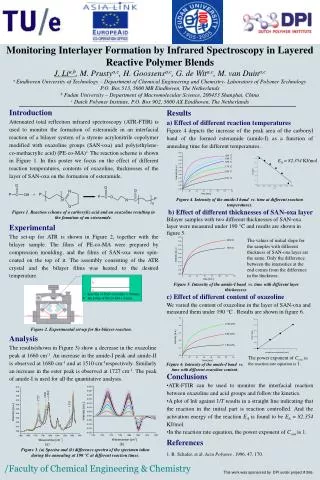
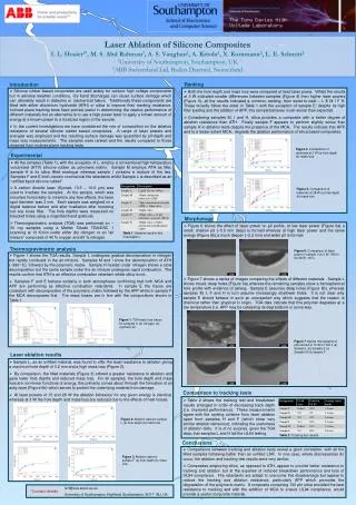
Laser Ablation of Silicone CompositesI. L. Hosier1*, M. S. Abd Rahman1, A. S. Vaughan1, A. Krivda2, X. Kornmann2, L. E. Schmitt21University of Southampton, Southampton, UK2ABB Switzerland Ltd, Baden-Daettwil, Switzerland Ranking Introduction • Silicone rubber based composites are used widely for outdoor high voltage components but in adverse weather conditions, dry band discharges can cause surface damage which can ultimately result in dielectric or mechanical failure. Traditionally these components are filled with either aluminium hydroxide (ATH) or silica to improve their tracking resistance. Inclined plane tracking tests have proved useful in determining the relative performance of different materials but an alternative is to use a high power laser to apply a known amount of energy at a known power to a localized region of the sample. • In the current investigations we have considered the role of composition on the ablation resistance of several silicone rubber based composites. A range of laser powers and energies was employed and the resulting surface damage was quantified by pit-depth and mass loss measurements. The samples were ranked and the results compared to those obtained from inclined plane tracking tests. • Both the hole depth and mass loss were compared at fixed laser power. Whilst the results at 3 W indicated smaller differences between samples (Figure 4) than higher laser powers (Figure 5), all the results indicated a common ranking, from worst to best – L E M I F H. These broadly follow the order in Table 1 with the exception of sample E; despite its high filler loading and the addition of APP, this sample behaves much worse than expected. • Considering samples M, I and H, silica provides a composite with a better degree of ablation resistance than ATH. Finally sample F appears to perform slightly worse than sample H in ablation tests despite the presence of the MCA. The results indicate that APP, and to a lesser extent MCA, degrade the ablation performance of silica based composites. Figure 4: Comparison of materials at 3 W (a) hole depth (b) mass loss Experimental • All the samples (Table 1), with the exception of L, employ a conventional high temperature vulcanized (HTV) silicone rubber as polymeric matrix. Sample M employs ATH as filler, sample H is its silica filled analogue whereas sample I contains a mixture of the two. Samples F and E both contain commercial fire retardants whilst Sample L is described as an “unfilled liquid silicone rubber”. • A carbon dioxide laser (Synrad, 10.5 – 10.6 µm) was used to irradiate the samples. At the sample, which was mounted horizontally to minimize any flow effects, the laser spot diameter was 3 mm. Each sample was weighed on a digital balance before and after irradiation after knocking out any loose filler. The hole depths were measured on bisected holes using a magnified hand graticule. • Thermogravimetric analysis (TGA) was performed on ~ 30 mg samples using a Mettler Toledo TGA/DSC 1 scanning at 10 K/min under either dry nitrogen or an “air mixture” composed of 40 % oxygen and 60 % nitrogen. Figure 5: Comparison of materials at 28 W (a) hole depth (b) mass loss Morphology • Figure 6 shows the effect of laser power on pit profile, at low laser power (Figure 6a) a small, shallow pit (~0.5 mm deep) is formed whereas at high laser power and the same energy (Figure 6b),a much deeper (~2.2 mm) and wider pit is formed. Table 1: Samples used in this investigation. Thermogravimetric analysis Figure 6: Comparison of laser power in sample I (a) 3 W, 1600 s (b) 28 W, 160 s • Figure 1 shows the TGA results. Sample L undergoes gradual decomposition in nitrogen but rapidly combusts in the air mixture. Samples M and I show the decomposition of ATH (~380 oC), followed by the polymeric matrix. Sample H heated under nitrogen shows a slow decomposition but the same sample under the air mixture undergoes rapid combustion. The results confirm that ATH is an effective combustion retardant whilst silica is not. • Samples F and E behave similarly in both atmospheres confirming that both MCA and APP are performing as effective combustion retardants. In sample E the traces are consistent with decomposition of the polymeric matrix followed by the APP whilst in sample F the MCA decomposes first. The mass losses are in line with the compositions shown in Table 1. • Figure 7 shows a series of images comparing the effects of different materials. Sample L shows broad, deep holes (Figure 6a) whereas the remaining samples show a hemispherical hole profile with evidence of ashing. Sample E assumes deep holes (Figure 6b), whereas samples M, I, F and H in turn assume increasingly shallower holes. It is not clear why sample E should behave in such an unexpected way which suggests that the reason is chemical rather than physical in origin. TGA data indicate that this polymer degrades at a low temperature (i.e. APP may be catalysing its degradation) in some way. Figure 1: TGA mass loss traces for samples in (a) nitrogen, (b) synthetic air Figure 7:Optical micrographs of pits formed at 15 W for 320 s (a) Sample L (b) Sample E (c) Sample M (d) sample F Laser ablation results • Sample L, as an unfilled material, was found to offer the least resistance to ablation giving a maximum hole depth of 3.2 mm and a high mass loss (Figure 2). • By comparison, the filled materials (Figure 3) offered a greater resistance to ablation and gave lower hole depths and reduced mass loss. For all samples, the hole depth and mass loss are non-linear functions of energy, this primarily comes about through the formation of an ashy layer (Figure 6b) which serves to protect the underlying material from damage. • At laser powers of 15 and 28 W the ablation behaviour for any given energy is identical, whereas at 3 W the hole depth and mass loss are reduced due to the effects of heat losses. Comparison to tracking tests • Table 2 shows the tracking test and breakdown results arranged in order of decreasing track depth (i.e. improved performance). These measurements agree with the ranking scheme from laser ablation apart from samples H and F (which show very similar ablation behaviour), indicating the usefulness of ablation tests. It is of no surprise, given the TGA data, that samples L and H fail the UL94 testing. Figure 2: Ablation data for sample L (a) hole depth (b) mass loss Table 2: Tracking test results Conclusions • Comparisons between tracking and ablation tests reveal a good correlation, with all the filled samples behaving better than an unfilled LSR. In one case, where discrepancies do occur, the ablation and tracking test results were very similar. • Composites employing silica, as opposed to ATH, appear to provide better resistance to tracking and ablation but at the expense of reduced breakdown performance and loss of UL94 compliance. Fire retardants are added to overcome this disadvantage but appear to reduce the tracking and ablation resistance, particularly APP which promotes the degradation of the polymeric matrix. A composite containing 100 phr silica provided the best resistance to tracking and with the addition of MCA to ensure UL94 compliance, would provide a useful composite material. Figure 3: Ablation data for sample F (a) hole depth (b) mass loss ILH@ecs.soton.ac.uk University of Southampton, Highfield, Southampton, SO17 1BJ, UK *Contact details :