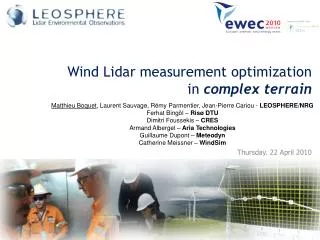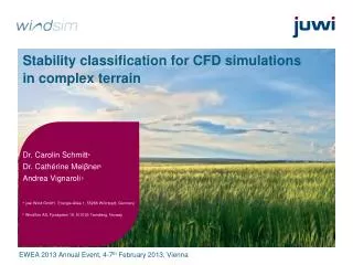
Point vs. VAD scans for complex terrain
180 likes | 303 Vues
This study explores conical scanning techniques using airborne Doppler wind lidar to profile winds in complex terrains. Over six years of operation on Navy aircraft, a bi-axis scanner was employed for adaptive scanning to capture organized atmospheric structures like rolls and updrafts. Field experiments were conducted over the Monterey Peninsula and during tropical cyclones, utilizing real-time data integration with satellite imagery. The research aims to optimize scanning strategies for effective data collection essential for meteorological modeling and validation.

Point vs. VAD scans for complex terrain
E N D
Presentation Transcript
Point vs. VAD scans for complex terrain G. D. Emmitt and C. O’Handley WG SBLW Destin, FL January 27-30, 2009
Overview The conical scan is the traditional pattern used to obtain vertical profiles of the wind field with an airborne Doppler wind lidar. Nadir or zenith pointing scanning wedges are ideal for this type of scan. A bi-axis scanner has been operated on a Navy Twin Otter for more than 6 years and was installed on a Navy P3 for use in a field experiment to study typhoons. The bi-axis scanner enables a broad range of scanning patterns. A subset of the possible patterns is critical to obtaining useful wind profiles in the presence of complex terrain or small (~ 100's of meters) organized atmospheric structures (rolls, updrafts, waves, etc). Several scanning strategies have been tested in flights over the Monterey Peninsula and within tropical cyclones. Combined with Google Earth (on-board) and satellite imagery overlays, new realtime adaptive scanning algorithms are being developed and tested.
Particle probes TODWL scanner STV Surface Temperature Sensor
The instrument • 2µm coherent detection (CTI MAG1A) • 2 mJ ; 500 Hz • 10 cm two axis scanner, side door mounted • GUI with realtime instrument control and data display • Range: .3 – 21km depending upon aerosols • Accuracy: < .10 m/s in three components • Weight: 700lb Power: 700 W
Scanning options • Nadir step-stare conical (3 – 12 positions) for vertical profiles for u, v, w & aerosols • Zenith step-stare (u, v, w) • Forward sweeping (prospecting for OLEs and shear layers ahead of aircraft • Nadir point scans (u,v,w) in complex terrain and organized flows (e.g. OLEs)
Acknowledgements • Most of our research on profiling in complex terrain and the implications to model validation/initialization has been funded under an SBIR through the Army Research Office (Dr. Walter Bach). • Additional funds were provided by the Integrated Program Office of NPOESS (Dr. Stephen Mango)