AIRBUS
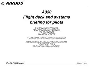
AIRBUS. A330 Flight deck and systems briefing for pilots THIS BROCHURE IS PROVIDED FOR INFORMATION PURPOSES ONLY AND ITS CONTENTS WILL NOT BE UPDATED. IT MUST NOT BE USED AS AN OFFICIAL REFERENCE. FOR TECHNICAL DATA OR OPERATIONAL PROCEDURES, PLEASE REFER TO THE

AIRBUS
E N D
Presentation Transcript
AIRBUS A330 Flight deck and systems briefing for pilots THIS BROCHURE IS PROVIDED FOR INFORMATION PURPOSES ONLY AND ITS CONTENTS WILL NOT BE UPDATED. IT MUST NOT BE USED AS AN OFFICIAL REFERENCE. FOR TECHNICAL DATA OR OPERATIONAL PROCEDURES, PLEASE REFER TO THE RELEVANT AIRBUS DOCUMENTATION STL 472.755/92 issue 4 March 1999
Contents 1. General 2. Flight deck layout 3. Electrical system 4. Hydraulic system 5. Flight controls 6. Landing gear 7. Fuel system 8. Engine controls 9. Auxiliary power unit 10. Automatic flight system 11. Environmental control system 12. Electronic instrument system 13. Radio management and communication 14. Central Maintenance System.
1. General 1.1
A330 General A330 general arrangement Typical cabin layout A330-200 256 seats A330-200 58.37 m 191ft 3in 9.37m 30ft 9in 18 sleeperette (62 in pitch) 42 Business (40 in pitch) 196 Economy (32 in pitch) 295 seats A330-300 10.7m 35ft 1.3in 60.304m 198ft 17.8m 58ft 5in 18 sleeperette (62 in pitch) 49 Business (40 in pitch) 228 Economy (32 in pitch) 6.67m 21ft 11in 22.18m 72ft 9in A330 fuselage cross-section 208.2in A330-300 5.287m 63.66 m 208ft 10in Passenger cabin 9.37m 30ft 9in 91.7in 65.7in True widebody l 2.33m 1.67m spaciousness and adaptability Lower cargo holds 10.7m 35ft 1.3in 60.304m 198ft 67in LD-3s Large, efficient, fullycompatible with existingworldwide air cargosystem l 1.702m 16.828m 55ft 2.5in 6.67m 21ft 11in 25.58 m 83ft 11in 125in 3.18m 222in 5.64m 1.2
A330 General Introduction Basic data • The medium to long-range A330 is an all-new, wide-body, twin-engine, twin-aisle aircraft. • The design combines high technology developed for the A320 and A340 with the wide experience gained from the A300 and A310 aircraft currently in world-wide service. - two-man crew operation with CRT displays - electrically signalled flight controls - sidestick controllers - full authority digital engine control (FADEC) - centralized maintenance system. • Since it’s introduction in December 1993 the aircraft is the most advanced medium to long-range airliner offering a major stride forward in airline profitability. • Certification basis includes : - JAR 25 at change 13 - JAR AWO at change 1 for CAT II and CAT III and autoland. - ICAO annex 16 chapter 3 for noise. A330-300 A330-200 217 000 kg 179 000 kg 169 000 kg 97 170lit 41 100 ft GE CF6-80E1A2 67 500 lb RR Trent 768 / 772 67 500 lb / 71 100 lb PW 4164 / 4168 64 000 lb / 68 000 lb 330 kt CAS/0.86 32/33LD3/11 pallets + bulk 19.7 m3 MTOW* MLW MZFW Max fuel capacity Max operating altitude Powerplants Design speeds Vmo/Mmo Underfloor cargo 230 000 kg 180 000 kg 168 000 kg 139 090 lit 41 100 ft GE CF6-80E1A4 70 000 lb RR Trent 772 71 100 lb PW 4168 68 000 lb 330 kt CAS/0.86 From 27LD3 to 3LD3 + 8 pallets + bulk 19.7 m3 As with the A319, A320, A321 and A340, it will incorporate all of the following features : * Max ramp weight 900 kg higher than MTOW 1.3
A330 General Aircraft design specifications 1. Design weights (see page 1.3) 2. Design speeds VMO= 330 kt CAS MMO = 0.86 VD= 365 kt CAS MD= 0.93 VB= 260 kt CAS MB= 0.78 VLO(landing gear) extension retraction VLE(Landing gear extended) 3. Slat and flap design speeds 4. Structural life (design aims) The objectives for primary structure fatigue life are as follows based on average block time of 4 hours : - design life goal …………………………. 20000 flights - threshold for initial inspection ………… 8 750 flights 5. Landing gear The design aim is 25000 cycles safe life operation in accordance with FAR and JAR. 6. Cabin pressure 250 kt CAS Lever position Config. No. Design speed VFE kt (CAS) Function Max nominal operational differential pressure Actuating cabin pressure of discharge valve Max relief valve overpressure Max negative differential pressure 8.33 psi ± 0.1 psi 8.85 psi ± 0.1 psi 9.25 psi 1.00 psi 574 mb ±7 mb 610 mb ± 7 mb 638 mb - 70 mb Climb/cruise/holding Holding Take-off Approach Take-off Take-off/approach Landing 0 1 1 2 3 Full 0 1 1 + F 1* 2 3 Full - 240 215 205 196 186 180 1.4
A330 General Aircraft design specifications 7. Fuel capacity A330-200 A330-300 Litres US gallons Litres US gallons 42 000 Inner tank LH 11 095 11 095 964 964 1 646 10 980 36 745 42 000 Inner tank RH 3 650 Outer tank LH 3 650 Outer tank RH 6 230 Center tank 41 560 Trim tank 139 090 Total 8. Pavement strength Max ramp weight and max aft CG. ACN Flexible pavement Rigid pavement Cat A 61 56 Cat B 66 61 Cat C 77 71 Cat D 105 95 Cat A 52 48 Cat B 61 55 Cat C 73 65 Cat D 85 76 A330-200 A330-300 Tyres radial - main gear 1400 mm x 530 mm x R23 - nose gear 1050 mm x 395 mm x R16 1.5
A330 General Weight and balance A330-200 CG limits A330-300 CG limits 1.6
A330 General Ground maneuvre capability Minimum turning radius Towing The A330 can be towed or pushed up to a nosewheel angle of 78° from the aircraft centre line at all weights up to maximum ramp weight without disconnecting the steering. Taxiing Minimum turning radii (with tyre slip) and minimum pavement width for 180° turn are as shown. Type of turn 2 Effective turn angle 62.3° Type of turn 1 Effective turn angle 78° Type of turn 2 Effective turn angle 64.5° Type of turn 1 Effective turn angle 77.95° A330-200 A330-300 Meter 4.72 34.27 23.24 36.29 29.26 32.89 (Feet) 15.478 112.4 76.26 119.04 96.07 107.91 Meter 11.65 43.58 25.62 42.99 31.20 36.45 (Feet) 38.23 143.0 84.06 141.06 102.37 119.6 Meter 12.10 47.16 26.78 43.36 34.26 38.01 (Feet) 39.7 154.7 94.3 142.3 112.4 124.7 (Feet) 15.53 125.1 86.9 120.9 106.2 113.5 Meter 5.342 38.13 26.49 36.96 32.37 34.60 Y A R3 R4 R5 R6 Y A R3 R4 R5 R6 X = 22.19 m / 72.8 ft X = 27.50 m / 90.23 ft Type of turn 1 : Asymmetric thrust differential braking (pivoting on one main gear) Type of turn 2 : Symmetric thrust no braking 1.7
A330 flight deck layout General provisions • As the A330 is a medium long-range aircraft the cockpit offers full provision for a 3rd occupant seat as well as a folding 4th occupant seat. 2.2
A330 flight deck layout Forward view FO boomset stowage FO boomset jack panel Overhead outlet Reading light Assist handle Ceiling light Sliding tables Window control handle Escape rope stowage Loudspeakers Sidestick Nose wheel steering CTL Hand microphone Ashtray Checklist stowage Roller sunblind Oxygen mask Oxygen mask Air conditioning outlet Waste bin Waste bin Checklist stowage Flash light Flight documents stowage Window outlets Normal checklist storage Briefcase stowage 2.3
A330 flight deck layout Rear view : right aft corner RAIN REPELLENT BOTTLE (OPTION) OXY MASK 4th OCCUPANT CONSOLE AXE Rear view : left aft corner OXY MASK LIFE VEST LIFE VEST JACK PANEL 3rd OCCUPANT CONSOLE HEADSET BOOMSET 2.4
A330 flight deck layout Pilots’ field of vision Visibility • Windows are designed to meet or exceed the Aerospace standard. • Geometry : - windshield panels : flat glass - lateral windows : curved acrylic. Pilots’ vision envelope 2.5
A330 flight deck layout Pilots’ field of vision Pilot’s eye position 25° 19°20’ 7ft 10.7in 2.40m 21ft 10.6in 6.67m 45ft 1.3in 13.75m 111° 135° Max. aft vision with head rotated about spinal column Pilot’s eye position 115° 1ft 9in 0.53m 62° 62° 135° With head moved 5 inches outboard 42° 42° 30° 30° 36° 36° 2.6
A330 flight deck layout Pilots’ field of vision - landing configuration CAT II DH = 100 ft • This geometry improves external aircraft monitoring, thereby increasing safety standards. - Downward visibility in the pilot axis is 20°. - Wing tips are visible from respective pilot stations. Aircraft A330-200 m (ft) A330-300 m (ft) V 120 (394) 120 (394) A 39.7 (132) 38.2 (127) 0 150 (493) 120 (394) RVR 270 (887) 240 (788) SVR 273 (897) 243 (798) q 5° 2.1° 2.1°pitch Pilot’s eyes q 20° cockpit cut-off angle A SVR 100ft 30m B C V (Visual segment) O (Obscured) RVR 2.7
A330 flight deck layout Control and indication panels (shaded) 2.8
A330 flight deck layout Main features • The main features are common with those developed for the A320 and A340 families : • The other features evolve directly from the concepts introduced with the A300/A310 family : sidestick controllers which leave the main instrument panel unobstructed six display units (DU) interchangeable, switchable and integrated into the same system architecture (EFIS/ECAM). ergonomic layout of panels, synoptically arranged according to frequency of use (normal, abnormal, emergency) within easy reach and visibility for both crew members philosophy of panels (e.g., “lights out” philosophy for overhead panel) principles of presentation of information (“need to know” concept) monitoring of systems through an Electronic Centralized Aircraft Monitor (ECAM) coherent system of colour coding for EFIS, ECAM and panel lights. 2.9
A330 flight deck layout Sidestick arrangement • Sidesicks are installed on the Captain’s and First Officer’s forward lateral consoles. • A dual pivot adjustable armrest behind each sidestick to facilitate control is fitted on each seat, with position indicators. Pitch adjustment The handgrip includes two switches : - A/P disconnect/sidestick priority push-button - Push-to-talk button Position indicator Neutral Radio Take-over PB (A/P disconnection or take-over from opposite sidestick) 2.10
A330 flight deck layout Sidestick operation • Control of the flight path is performed by the Electronic Flight Control System (EFCS) which links the trajectory order with aerodynamic data to stabilize the aircraft and protect it from prohibited attitudes. • Moving the sidestick results in “setting the aircraft trajectory” with a certain level of “g” for the requested manoeuvre depending on the amount of sidestick movement. • Accuracy of movements is very precise since backlash and friction are negligible. Sidestick released : return to neutral Sidestick released : return to neutral 2.11
A330 flight deck layout Main instrument panels 2.12
A330 flight deck layout Captain and First Officer panels • The CAPT and F/O panels are mirror images of each other : both incorporate two side-by-side Display Units (DUs) (7.25 in x 7.25 in) : . a Primary Flight Display (PFD) . a Navigation Display (ND). • This arrangement provides : - better visibility on all DUs in normal configuration and in case of reconfiguration (PFD ND or ECAM ND) - the option to install a sliding table and a footrest in front of each pilot. • ThePFD includes the complete Basic T with : - attitude - airspeed/Mach (with all upper and lower limits) - altitude/vertical speed - heading - AFS status - ILS deviation/marker - radio altitude. • The ROSE mode (ILS, VOR or NAV) : aircraft symbol in screen centre, with radar availability - ARC mode : heading up, horizon limited to a 90° forward sector, with radar availability - PLAN mode : north up, display centered on selected waypoint. • Engine display : in case of a total DMC/ECAM failure, each pilot may display the ENG STBY page on his ND. Note : In ROSE-NAV, ARC, and PLAN modes, MAP data from FMS is presented. 2.13
A330 flight deck layout Main centre panel The centre panel groups : - two DUs, one above the other, which are interchangeable with the CAPT and F/O DUs : • Engine Display (DU 1), showing : - the main engine parameters (N1, EGT, N2 for GE engines ; EPR, EGT, N1, N2 for PW engines ; (EPR, TGT, N1, N3 for RR engines) - N1 (EPR) limit, N1 (EPR) command - total fuel - the flaps and slats position - memo and warning • System Display (DU 2) showing : - an aircraft system synoptic diagrams page - or the aircraft status (list of all operationally significant items) - standby instruments - landing gear control and indications (including brakes) - clock. 2.15
A330 flight deck layout Glareshield • The Flight Control Unit (FCU) provides short-term interface between the Flight Management and Guidance Computer (FMGC) and crew for : - engagement of A/P, A/THR - selection of required guidance modes - manual selection of flight parameters SPD, MACH, ALT, V/SPD, HDG or track. • The EFIS control panels for : - selection of desired ND modes (ROSE-ILS, -VOR, - NAV, ARC, PLAN, ENG) and ranges - selection of baro settings. • The master warning, master caution, autoland and sidestick priority lights. 2.16
Switching control panel ECAM control panel Multipurpose Multipurpose CDU CDU Radio Radio management management Power panel panel levers Audio control Audio control panel panel Flood ACMS DFDR Lighting light print event control panel Engine master ATC TCAS Weather Radar Engine start Speed brake Flaps/slats Parking brake Multipurpose CDU Multipurpose printer Space Rudder trim panel Handset A330 flight deck layout Central pedestal In addition to the thrust levers and the engine control functions, the main features on the pedestal are : • the Multipurpose Control and Display Units (MCDU) for flight management functions and various other functions such as data link, maintenance, etc. • the Radio Management Panels (RMP) for tuning all radio communications and the radio navigation as a back-up to the normal operation through the Flight Management and Guidance Computers (FMGC). • the electrical rudder trim • the parking brake control • the speedbrake and flap control levers. 2.17
A330 flight deck layout Overhead panel • The overhead panel has a “single slope”. • All controls on the overhead panel can be reached by either pilot. • Two main zones are separated by protective padding. • The push-button philosophy is identical to that already applied on existing Airbus aircraft. Space Space Space Space Reset panel Reading light - Forward zone : - for most frequently used functions - for system controls : arranged in three main rows : - centre row for engine-related systems arranged in a logical way - lateral rows for other systems. - Aft zone, not used in flight, mainly for a small maintenance panel corresponding to some maintenance controls. Reading light Reset panel Maintenance panel Space Light Space CVR panel ADIRS Engine Fire Audio control panel Hydraulic power APU Fire Radio managt panel Flight control Fuel Flight control Fuel EVAC Cargo air cond. Electrics Emer elec GPWS Cargo smoke Oxygen RCDR Air conditioning Ventilation Calls Engine start Anti ice Cabin press Interior lighting Rain Wiper RPLNT Wiper Rain RPLNT APU EXT lighting Signs 2.18
A330 electrical system Electrical power generation The electrical power generation comprises : • Two engine-driven AC generators, nominal power 115 kVA • One auxiliary power unit (APU) AC generator nominal 115 kVA • One emergency generator (Constant Speed Motor /Generator or CSM/G), nominal power 8.6 kVA, hydraulically driven by the Green system. • One static inverter fed by two batteries and working either on the ground or when CSM/G inoperative. • Two ground connectors, power 90 kVA • DC network supplied via two main Transformer Rectifier Units (200 A) and one essential (100 A). A fourth TR (100 A) is dedicated to APU start or APU battery charging. • Three batteries nominal capacity 37 Ah, 28 V each : - Two batteries used : - One dedicated to APU start • in emergency configuration to feed some equipment during RAT deployment or when CSM/G not operating. • On ground to provide an autonomous source. 3.2
A330 electrical system Distribution - normal configuration AC distribution network • In normal configuration, each engine-driven generator supplies its associated AC BUS. • The AC ESS BUS is normally supplied from AC BUS 1. DC distribution network • In normal configuration, normal DC systems are split into two networks : DC BUS 1 in parallel with DC BAT BUS and DC BUS 2. • Each DC network is supplied by its own TR. • More specifically, ESS TR systematically feeds DC ESS BUS, which allows a better segregation between DC 1 and DC 2. • Two batteries are connected to the DC BAT BUS via the Battery Charge Limiter (BCL). • Each battery has its own HOT BUS bar (engine/APU fire squib, ADIRS, CIDS, PRIM and SEC computers, slide warnings, parking brake, etc). • The third battery is dedicated to APU starting. 3.3
ELEC DC DC BAT DC APU BAT 1 BAT 2 APU BAT 25 V 26 V 25 V 0 A 0 A 0 A DC 1 DC ESS DC 2 SHED LND RCVRY TR 1 ESS TR TR 2 APU TR 0 V 0 V 0 V 0 V 0 A 100 A 0 A 0 A AC1 EMER GEN AC2 AC2 A330 electrical system Distribution - abnormal configurations Generator failure • if one generator fails, another will automatically take over : • if APU operative, APU generator will take over • if APU generator not available, the other engine generator will take over. - In case of total loss of all main generators : • the EMER GEN will deliver 8.6 kVA since the Green hydraulic system is still powered by engine-driven pumps or - In case of loss of all engines : • the EMER GEN will deliver 3.5 kVA since the Green hydraulic system is then powered by the RAT ; in this case the batteries take over when slats are extended. TR failure - if one TR fails, the other will automatically take over its corresponding DC network via DC BAT BUS, - In case of double TR failure : • TR 1 and 2 : DC BUS 1 and DC BUS 2 are lost • TR 1 (or 2) and ESS TR : The remaining TR supplies DC BUS 1 + 2 and DC BAT BUS ; the DC ESS BUS is lost. TOTAL LOSS OF ALL MAIN GEN 3.4
A330 electrical system Control and display Overhead panel ECAM 3.5
C/B ECMU1 VOLT SNSG …………………. SFCC1 NORM DCBUS AVAI ………... HYD PUMP G ENG2 …………………. ANTI ICE ENG2 ……………………….. DU SWTG CAPT ND …………………. HYD PUMP B ENG1 ………………….. ADIRU1 155VAC ……………………… ANTI ICE PITOT 1 OR 3 …………….. 303PP ………………………………….. BUS 1/3 TIE CNTOR …………………. ANTI ICE 1 OR 3 PHC ……………….. EXTRACT FAN AVNCS ………………. ADIRU1 AOA1 26VAC ……………….. APU TR …………………………………. SWTG FUEL BUS …………………….. AUDIO ACP CAPT …………………….. AIR BLEED VLV ENG2 ……………….. XFEED VLV ENG1 MOT1-2 ………….. X1 X3 X44 W2 S2 U15 C8 D10 715VU X12 N21 J21 M80 5000VU W15 A50 D12 C15 4XM 10CW 4JG2 2DN2 9WK1 1JB 4FP1 4DA1 9PB 10PC1 2DA3 1HQ 5FP1 3PU3 8PR 4RN1 3HA2 40E1 A330 electrical system Circuit - breaker monitoring • Circuit-breakers are installed in the avionics bay area below the cockpit. • Circuit-breakers are monitored by the CBMU (Circuit-Breaker Monitoring Units) which output the identification and status of each circuit-breaker. • A specific C/B page is provided on the ECAM. • Computer resets can be performed via system controls. 3.6
A330 hydraulic system Architecture * 4.2
A330 hydraulic system General • Three fully independent systems : Green, Blue, Yellow (nominal pressure at 3000 psi). • Normal operation : They are managed by the HSMU (Hydraulic System Monitoring Unit) which ensures all autofunctions (electrical pumps, RAT, monitoring, etc) ; manual override is available on the overhead panel. - one handpump on the Yellow system for cargo doors operation when no electrical power is available. • Abnormal operation : in the event of one engine failure, the Green electrical pump runs automatically for 25 seconds when landing gear lever is selected up. in the event of engine 2 failure, the Yellow electrical pump runs automatically when flaps are not retracted. In the event of both engine failure, RAT deployment will be automatically controlled by the HSMU to pressurize the Green system. four engine-driven pumps, two of which are for the Green system three electrical pumps that can act automatically as back-up 4.3
A330 flight controls - EFCS Electronic Flight Control System (EFCS) Surfaces : • all hydraulically activated • all electrically controlled • mechanical back-up control : - rudder - Trimmable Horizontal Stabilizer 5.2
A330 flight controls - EFCS General The A330 fly-by-wire system is being designed to make this new aircraft more cost effective, safer and more pleasant to fly, and more comfortable to travel in than conventional aircraft. Basic principles • A330 flight control surfaces are all : - electrically controlled - hydraulically activated • Stabilizer and rudder can be mechanically controlled. • Sidesticks are used to fly the aircraft in pitch and roll (and indirectly through turn coordination, in yaw). • Pilot inputs are interpreted by the EFCS computers for moving the flying controls as necessary to achieve the desired pilot commands. • Regardless of pilot inputs, the computers will prevent : - excessive maneuvres - exceedance of the safe flight envelope. 5.3
A330 flight controls - EFCS Computers • three flight control primary computers (PRIM) which can process all three types of control laws (Normal, Alternate, Direct) • two flight control secondary computers (SEC) which can process the Direct Control Law. These computers perform additional functions including : • speebrakes and ground spoiler command • characteristic speed computation (PRIM only). Electrical control of the main surfaces is achieved by two types of computers : High-lift devices are commanded by two Slat/Flap Control Computers (SFCC). The SFCCs also command the aileron droop via the primary or secondary computers. In order to provide all required monitoring information to the crew and to the Central Maintenance System (CMS), two Flight Control Data Concentrators (FCDC) acquire the outputs from the various computers to be sent to the ECAM and Flight Data Interface Unit (FDIU). These two FCDCs ensure the electrical isolation of the flight control computers from the other systems. 5.4
A330 flight controls - EFCS Power sources Electrical power supply The flight control computers (primary, secondary and Flight Control Data Concentrator) are fed by various DC busbars. This ensures that at least two flight control computers are powered in the event of major electrical power losses such as - failure of two main systems or - electrical emergency configuration (CSM-G) or - battery-only supply. Normal Emergency DC ESS HOT AC ESS AC DC Primary 1 Primary 2 Primary 3 Secondary 1 Secondary 2 FCDC 1 FCDC 2 X X X (BACK UP) X X X X (BACK UP) X (BACK UP) X (SHED) X 5.5
A330 flight controls - EFCS Power sources Hydraulic power supply Three hydraulic circuits (Green, Yellow, Blue) power the flight controls. System circuit Green Yellow Blue Power source 2 engine (N° 1 and 2) - driven pumps 1 electropump 1 RAT 1 engine (N° 2) - driven pump 1 electropump 1 engine (N° 1) - driven pump 1 electopump The distribution to the various control surfaces is designed to cover multiple failure cases. 5.6
A330 flight controls - EFCS Safety objectives Safeguards were designed for protection against : Loss of pitch control - extremely improbable (<10-9) Loss of elevators - extremely remote (< 10-7) Loss of roll control - extremely improbable Permanent loss of THS - extremely improbable Rudder loss or runaway - extremely improbable In order to satisfy these objectives, the following architecture applies : - electrical signalling for spoilers, elevators and ailerons - electrical and mechanical signalling in parallel for rudder and THS. 5.7
A330 flight controls - EFCS Dispatch objectives The basic objective is to allow dispatch of the aircraft with at least one peripheral or computer failed in order to increase the dispatch reliability without impairing flight safety. Systems 3 IRS 2 yaw rate gyros 3 PRIM 2 SEC 3 ADR 3 IR - 2 Nz accelerometers 2 FCDC 3 PRIM/2 SEC Electro hydraulic and electro actuators Dispatch situation Maximum 1 inoperative or “off” Maximum 1 inoperative or “off” Maximum 1 inoperative or “off” Maximum 1 inoperative or “off” Maximum 1 inoperative or “off” Maximum 1 inoperative if it is not connected to 2 computers No-go items are inboard aileron, elevator and yaw damper actuators. 5.8
A330 flight controls - EFCS Design principles The two secondary computers (SEC) : • are able to process direct laws only • either SEC can be the master in case of loss of all primary computers • each SEC can control up to 10 servo-loops simultaneously ; each can provide complete aircraft control. Electrically controlled hydraulic servo-jacks can operate in one of three control modes depending upon computer status and type of control surface : • Active : the servo-jack position is electrically controlled • Damping : the servo-jack position follows the surface movement • Centering : the servo-jack position is maintained neutral. Two types of flight control computers : • PRIM (two channels with different software for control/monitoring). SEC (two channels with different software for control/monitoring). • Each one of these computers can perform two tasks : - process orders to be sent to other computers as a function of various inputs (sidestick, autopilot…) - execute orders received from other computers so as to control their own servo-loop. The three primary or main computers (PRIM) : • process all control laws (Normal, Alternate, Direct) as the flight control orders. • One of the three PRIM is selected to be the master ; it processes the orders and outputs them to the other computers PRIM 1, 2 and 3, SEC 1 and 2) which will then execute them on their related servo-loop. • The master checks that its orders are fulfilled by comparing them with feedback received ; this allows self-monitoring of the master which can detect a malfunction and cascade control to the next computer. • Each PRIM is able to control up to eight servo-loops simultaneously ; each can provide complete aircraft control under normal laws. 5.9
A330 flight controls - EFCS Schematic diagram 5.10