Download
1 / 4
40 likes | 74 Vues
Device to Device D2D communication allows user devices to directly communicate with each other. D2D using smart antenna will reduce the interference and also reduce the power with respect to distance between the devices. This D2D communication generates directional signal transmission between D2D pairs and reduces the interference between other users. This study also proposes the study of 4x4 MIMO microstrip patch antenna for 5G cellular network. This antenna operates at the frequency of 3.3 4.2 GHZ and its resonant frequency is 3.75GHZ. Rogers RO4350B lossy with thickness of 0.101mm and dielectric constant has been used as the antenna substrate. The simulations results shows that the proposed antenna design and it explains about the beam forming concepts that provides the need of D2D communication for 5G application. The antenna is steered to particular direction with the help of beam forming algorithm. This shows that such scheme improves the system capacity compared to the traditional one by focusing it in a desired direction. This method will provide security to the data, increases the network efficiency, consume less power and traffic made by the signals is reduced. Dr. Arunachalaperumal | B. S. Aparna | R. Renugadevi "Design and Simulation of Smart Antenna for D2D Communication" Published in International Journal of Trend in Scientific Research and Development (ijtsrd), ISSN: 2456-6470, Volume-4 | Issue-4 , June 2020, URL: https://www.ijtsrd.com/papers/ijtsrd31609.pdf Paper Url :https://www.ijtsrd.com/engineering/electronics-and-communication-engineering/31609/design-and-simulation-of-smart-antenna-for-d2d-communication/dr-arunachalaperumal<br>

E N D
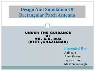
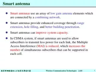
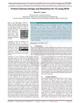
International Journal of Trend in Scientific Research and Development (IJTSRD) Volume 4 Issue 4, June 2020 Available Online: www.ijtsrd.com e-ISSN: 2456 – 6470 Design and Simulation of Smart Antenna for D2D Communication Dr. Arunachalaperumal1, B. S. Aparna2, R. Renugadevi2 1Professor, 2U G scholar, 1,2Department of Electronics and Communication Engineering, 1,2S.A. Engineering College, Poonamalee-Avadi Main Road, Thiruverkadu, Chennai, Tamil Nadu, India ABSTRACT Device-to-Device (D2D) communication allows user devices to directly communicate with each other. D2D using smart antenna will reduce the interference and also reduce the power with respect to distance between the devices. This D2D communication generates directional signal transmission between D2D pairs and reduces the interference between other users. This study also proposes the study of 4x4(MIMO) microstrip patch antenna for 5G cellular network. This antenna operates at the frequency of 3.3-4.2 GHZ and its resonant frequency is 3.75GHZ. Rogers RO4350B (lossy) with thickness of 0.101mm and dielectric constant substrate. The simulations results shows that the proposed antenna design and it explains about the beam forming concepts that provides the need of D2D communication for 5G application. The antenna is steered to particular direction with the help of beam forming algorithm. This shows that such scheme improves the system capacity compared to the traditional one by focusing it in a desired direction. This method will provide security to the data, increases the network efficiency, consume less power and traffic made by the signals is reduced. KEYWORDS: Device to Device communication, Smart antenna, Rogers, Beam forming How Arunachalaperumal | B. S. Aparna | R. Renugadevi "Design and Simulation of Smart Antenna for D2D Communication" Published in International Journal of Trend in Scientific Research and Development (ijtsrd), ISSN: 2456-6470, Volume-4 | Issue-4, June 2020, pp.1512- 1515, www.ijtsrd.com/papers/ijtsrd31609.pdf Copyright © 2020 by author(s) and International Journal of Trend in Scientific Research and Development Journal. This is an Open Access article distributed under the terms of the Creative Commons Attribution License (CC (http://creativecommons.org/licenses/by /4.0) to cite this paper: Dr. has been used as the antenna IJTSRD31609 URL: BY 4.0) I. Antennas play a vital role in a communication system and it is used in both transmission and reception of radio signals. It is a metallic object, made up of a wire or collection of wires. The antenna at the transmitter side converts electrical energy into electromagnetic waves, whereas a receiver side antenna converts electromagnetic waves into electrical energy. The design of an antenna depends on directivity of the beam and frequency of carrier waves. Antennas are used in applications like radio and television broadcasting, peer to peer communication, wireless LAN, cell phones, radar etc., Device to Device communication allows user devices proximity (nearness) to directly communicate with each other. D2D allows users to experience increased data rate and reduced energy consumption. It is currently being specified by 3GPP in LTE, focussing on public safety applications and proximity communication between nearby mobile devices will improve spectrum utilization. D2D is exploiting the potential of full- duplex communications. Integration of several antenna technologies and D2D enhances the capacity and coverage of cellular networks. Device to Device communication is a short range technology in communication, in which data is exchanged between devices. Combining the cellular communication and D2D can get spectrum efficiency. Beam INTRODUCTION: forming technique is seem to be good for D2D communication. Factors used for computing beam forming are gain, position, phase angle, length of the beam, number of patterns and interference. In beam forming technique the beam pattern, main beam and side lobe are calculated. Smart antenna comprises of one or more antennas. It is an antenna system which dynamically reacts to its surrounding for providing good signals and usage of frequencies for wireless communication. There are variety of smart antenna used for several applications. There is a need for smart antenna because of limited allocation of spectrum, mobility of users give rise to signal fading, power constrains in mobile devices, and interference due to frequency reuse. MIMO (Multiple Input Multiple Output) communication methods are based for using a number of transmit antennas and its signals are received by a number of receivers. Hence there are number of paths between the transmitter and receiver. The MIMO system increases the channel capacity and allows several users to access various services at the same time. MIMO technique is a proven solution for the disadvantages in short range communication. Antenna dimensions and isolation coefficients are the two major criteria to be considered in MIMO antenna design. based service. Direct @ IJTSRD | Unique Paper ID – IJTSRD31609 | Volume – 4 | Issue – 4 | May-June 2020 Page 1512
International Journal of Trend in Scientific Research and Development (IJTSRD) @ www.ijtsrd.com eISSN: 2456-6470 II. The proposed antenna is printed on a Roger RO4350B substrate having dielectric constant of 3.8, a tangent loss of 0.0037 and thickness of 0.101mm and simulated in the frequency range from 3.3 to 4.2GHZ. In this design four patches are placed on a single substrate and the feed line of each patch is designed with an input impedance of 50 ohms. Each patchis connected using the feed line. The height of the transmission path is 1.5 mm and the width of the feed is calculated as 3.4mm. The steps for designing microstrip patch antenna is given below, Step 1: To calculate the Width (W) Antenna design: Figure 1: MIMO 4x4 Antenna design Figure 1 shows the design of 4x4 MIMO antenna. Multiple Input Multiple Output (MIMO) increases signal-capturing power at the receiver side by enabling theantennas to combine data streams arriving at different times and from different paths. Here these 4 antenna act as a transmitter as well as receiver. It enables the transmission of more than one signal to one user via the same set of air interface resources. III. SIMULATION RESULTS The antenna was designed and simulated using CST Studio Suite. The performance of the antenna has been observed and the simulation results of return loss, Voltage Standing Wave Ratio (VSWR), bandwidth obtained and directivity are shown in the following figures. A.S Parameter In an electrical system a scattering parameter generally describes the relationship between input-output ports. The S Parameter of this antenna like return loss, reflection coefficient can be obtained from this Figure 2. The obtained resonant frequency is 3.6 GHZ and return loss is -40.045 dB. The Bandwidth calculated from S Parameter is 40MHZ as shown in Figure 2. Step2: To calculate the Effective Dielectric Constant, + Step 3: To calculate the Effective length, Step 4: To calculate the length extension ΔL, Step 5: To calculate the actual length of the patch, Where width respectively. is incremental length of patch, C is the speed of light in free space which is 10^8(m/s), h is the substrate height or thickness. Here the thickness of the substrate is taken as 2mm. The gap between patch and feed (Gpf) is taken as 1mm and the material used for the ground is copper which is made at the bottom of substrate and its thickness is taken as 2mm in the proposed design. The values of different parameters is shown in table 1. TABLE 1: Microstrip Antenna Specification Parameters Ground length(Lg) Ground Width(Wg) Substrate length(L) Substrate Width(W) Patch Length(Lp) Patch Width(Wp) Transmission path length Transmission path width Thickness of substrate From the specification in Table 1 the antenna is designed as shown in Figure 1 , L, W represent resonant frequency(HZ), length, is a effective dielectric constant, Values(mm) 79 59 79 59 35 23 35 45 2 Figure 2 S Parameter of Designed Antenna B.VSWR Voltage Standing Wave ratio (VSWR) is a function of reflection coefficient which describes the measure of how much power is delivered to an antenna. The value of VSWR is always real and positive number of antenna. Low value of VSWR indicates a good antenna match. Here the VSWR value of this antenna is 1.05. Since the value of VSWR is under 2 it is considered for antenna applications. @ IJTSRD | Unique Paper ID – IJTSRD31609 | Volume – 4 | Issue – 4 | May-June 2020 Page 1513
International Journal of Trend in Scientific Research and Development (IJTSRD) @ www.ijtsrd.com eISSN: 2456-6470 Beamforming uses the science of electromagnetic interference that makes a fifth generation(5G) connection more accurate. To describe a system a term MIMO is used where multiple transmitters or multiple receivers are present. This beamforming technique focuses a signal only in a specific direction where the receiver is present rather than transferring the signal in all direction. This paper explains about the beamforming for MIMO-OFDM systems. There are different parts of systems such as single-input-multiple- output (SIMO) or multiple-input-single-output (MISO) system. This paper illustrates a 8-element uniform linear array (ULA) is implemented at the base station as the transmitter and the receiver is a mobile unit with a single antenna. The configured system is given below, a power transmitted is 8 watts and a gain transmitted is -8 dB. The receiver mobile signal is positioned and located away 2750 meters from the transmitter. An interference with a power of 1 watt and a gain of -20 dB is located at 9000 meters away and 20 degrees off the transmitter's side. Figure 6 shows the output of a beam which steers in a desired direction. Figure 3 VSWR Measurement Of Antenna C.Directivity Directivity is a measure of how directional an antenna’s radiation pattern is. It is a fundamental parameter of antenna. The directivity of main lobe of antenna is 7.32 dBi at 12 degree theta direction. The side lobe level is -9.1 dB as shown in Figure 4. The antenna radiation pattern in 3Dimention is shown in Figure 5, which gives the value of antenna gain as 7.57 and the efficiency of the antenna is obtained as -9.522 or 33.4118 %. Figure 4 Radiation Pattern of Antenna Figure 6 Beamforming for MIMO system Signal transmission is done by configuring the system’s transmitter. The components present in transmitter sub- system are convolution encoder, the scrambler, and the QAM modulator. Before the radiation the message is converted in to a information bit stream and then passed. A data is carried in OFDM by multiple sub-carriers. The data stream is radiated in the array from a antenna then the array is steered towards a given steering angle. Signal reception is done by the receiving antenna, that collects both the interference signal and propagation signal.To recover the original information, the MIMO-OFDM system performs different stages at the receiver side they are, OFDM de-modulator, Viterbi decoder, QAM de- modulator and equalizer. A decoded output is compared with the original message stream. While comparing the Bit error rate(BER) is high for this communication system. It refers that the mobile is Figure 5 Radiation Pattern of Antenna in 3D Beamforming The wireless communication widely uses a smart antenna, beacause the smart antenna has a ability to increase the capacity and network coverage of a communication system. The two main functions performed by smart antenna are direction of arrival(DOA) and beamforming. Using this beamforming algorithm smart antenna forms a main beam towards the users desired direction and does not send the beam in the interference direction. IV. @ IJTSRD | Unique Paper ID – IJTSRD31609 | Volume – 4 | Issue – 4 | May-June 2020 Page 1514
International Journal of Trend in Scientific Research and Development (IJTSRD) @ www.ijtsrd.com eISSN: 2456-6470 [2]Nagaraj Hanchinamani1 and Dr. C.R. Byrareddy “ A Multiband MIMO Microstrip Patch Antenna for Wireless Applications” in International Journal for Research in Applied Science & EngineeringTechnology (IJRASET) aligned with the steering direction, shows that the BER is improved. Figure 7 shows the constellation diagram, [3]Constantine Balanis A john book: “Antenna theory Analysis and design” [4]Mohammed A. Almagboul, FengShu, Yaolu Qin, Xiaobo Zhou, Jin Wang, YuwenQian, and Kingsley Jun ZouNational “An Efficient Hybrid Beamforming Design for Massive MIMO Receive Systems via SINR Maximization Based on an Improved Bat Algorithm” NaturalScience Foundation of China [5]Jayarenjini N, and UnniC A Novel Microstrip “Slotted Patch Antenna using Different Dielectric Substrates for Multiple Applications”, International Journal of Applied Engineering Research ISSN 0973-4562 Volume 13, Number 16 (2018) pp. 12591-12596 [6]Broad band India forum “Roadmap for 5G in India”. [7]Amara Algorithms for Smart Antenna Systems” WSEAS transactions on communications. PrakasaRao, “Adaptive Beamforming Figure 7 Constellation diagram V. In this paper 4x4 MIMO microstrip patch antenna has been designed and simulated for 5G applications. The designed antenna works in the frequency range of 3.3GHZ to 4.2GHZ. It has a return loss of -40.045dB at 3.6GHZ and the gain value is 7.57 and the efficiency is -9.522 or 33.441%. Antenna is designed with beamforming algorithm. This algorithm helps to steer the antenna in a particular direction, which improves the system capacity. REFERENCES [1]Qing Shen1,a, Tiantian Guo1, and Yaozhi Du1“ Reconfigurable Antenna Beamforming in Device to Device Communication journal in Applied Mechanics and Materials Vol 740 (2015) pp 819-822 [8]Manoj Thakur and VikramPratapsingh “Review of Different Structure and application of Microstrip Patch Antenna” International Journal of Engineering and Management Research Volume-4, Issue-4, August- 2014, ISSN No.: 2250-0758 CONCLUSION [9]RafiaNishatTomaa*, MdNazmulHasana “Analysis the effect of Changing Height of the Substrate of Square Shaped Microstrip Patch Antenna on the Performance for 5G Application” I. J. Wireless and Microwave Technologies, 2019, 3, 33- 45 Published Online MECS(http://www.mecs-press.net) ImtiajAhmmedShohagha, May 2019 in [10]https://www.mathworks.com/help/phased/examples /beamforming-for-mimo-ofdm-systems.html @ IJTSRD | Unique Paper ID – IJTSRD31609 | Volume – 4 | Issue – 4 | May-June 2020 Page 1515