Download
1 / 11
110 likes | 137 Vues
Voltage fluctuations resulting from variable output power of renewable energy sources are strictly challenging power quality in distributed generation systems. This paper presents a control method for distributed static synchronous compensator D STATCOM to alleviate variation of both positive and negative sequence voltages. The D STATCOM simultaneously operates as fundamental positive sequence admittance and fundamental negative sequence conductance to restore the positive sequence voltage to the nominal value as well as reduce the negative sequence voltage to an allowable level. Both admittance and conductance are dynamically tuned to improve voltage regulation performances in response to load changes and power variation of renewable sources. A proportionalresonant current regulator with selectively harmonic compensation is realized to control the fundamental current of the D STATCOM as well as reduce the harmonic current, which could be an advantage in practical applications due to high voltage distortion in low voltage micro grids. Voltage regulation performances are discussed for different D STATCOM locations as well as different D STATCOM currents. Computer simulations and laboratory tests validate effectiveness. CH. Venkata Krishna | N. S. Kalyan Chakravarthi "Impact of Positive Sequence Admittance and Negative Sequence Conductance of D-Statcom to Compensate Variations in Voltage Levels in Distributed Generation Systems" Published in International Journal of Trend in Scientific Research and Development (ijtsrd), ISSN: 2456-6470, Volume-2 | Issue-1 , December 2017, URL: https://www.ijtsrd.com/papers/ijtsrd5919.pdf Paper URL: http://www.ijtsrd.com/engineering/electrical-engineering/5919/impact-of-positive-sequence-admittance-and-negative-sequence-conductance-of-d-statcom-to-compensate-variations-in-voltage-levels-in-distributed-generation-systems/ch-venkata-krishna<br>

E N D
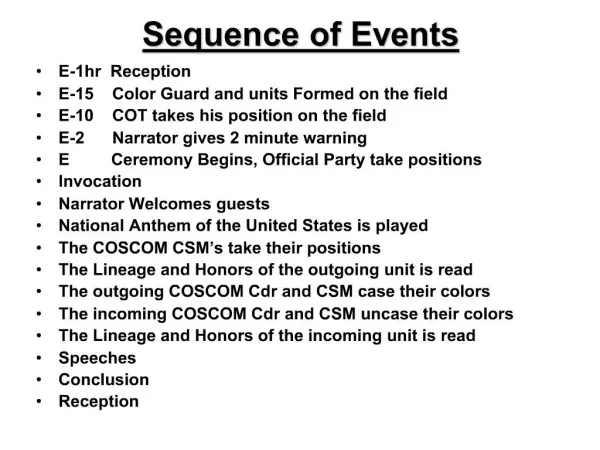
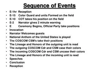
International Research Research and Development (IJTSRD) International Open Access Journal International Journal of Trend in Scientific Scientific (IJTSRD) Access Journal ISSN No: 2456 - 6470 | www.ijtsrd.com | Volume Impact of Positive Sequence Admittance and Negative Sequence -Statcom to Compensate Variations in Voltage Levels in Distributed Generation Systems ISSN No: 2456 | www.ijtsrd.com | Volume - 2 | Issue – 1 Impact of Positive Sequence Admittance and Negative Sequence Conductance of D- Voltage Levels in Distributed CH. Venkata Krishna M. Tech scholar, Department of Electrical and Electronics Engineering, Kakinada Institute of Technological Science , Ramachandrapuram ABSTRACT Impact of Positive Sequence Admittance and Negative Sequence Statcom to Compensate Variations in Generation Systems N. S. Kalyan Chakravarthi Asst. Prof., HOD, Department of Electrical and Electronics Engineering, Kakinada Institute of Technological Science , Ramachandrapuram Technological Science , Ramachandrapuram hakravarthi of Electrical and Asst. Prof., HOD, Department of Electrical and Electronics Engineering, Kakinada Institute of Electronics Engineering, Kakinada Institute of Technological Science , Ramachandrapuram I. INTRODUCTION Voltage fluctuations resulting from variable output power of renewable energy sources are strictly challenging power quality in distributed systems. This paper presents a control method for distributed static synchronous compensator (D STATCOM) to alleviate variation of both positive and negative-sequence voltages. The D simultaneously operates as fundamental positive sequence admittance and fundamental negative sequence conductance to restore the positive sequence voltage to the nominal value as well as reduce the negative-sequence voltage to an allowable level. Both admittance and conductance are dynamically tuned to improve voltage regulation performances in response to load changes and power variation of renewable sources. A proportional–resonant current with selectively harmonic compensation is realized to control the fundamental current of the D as well as reduce the harmonic current, which could be an advantage in practical applications due to high voltage distortion in low-voltage Voltage-regulation performances are discussed for different D-STATCOM locations as well as different D-STATCOM currents. Computer simulations and laboratory tests validate effectiveness. Voltage fluctuations resulting from variable output power of renewable energy sources are strictly quality in distributed-generation High penetration level of renewable energy sources and distributed generation (DG) plants faces new challenges in the operation of transmission and distribution networks .The growing installed power from DG plants has led to a change in the requirements for ancillary services, particularly during grid faults. Among these new services, voltage control in wind plants, photovoltaic parks and other large- scale power plants is gaining increasing attention due to its capability to improve grid efficiency, safety and reliability in a distributed manner. A voltage sag is a perturbation in the grid voltages characterized by a on in the magnitude of one or several phases. The effects of such disturbances are important in terms of economic losses, malfunction of devices connected to the grid and in extreme cases, blackouts. To alleviate the adverse effects of grid des from the network system operators dictate the behavior of DG plants. The D-STATCOM simultaneously operates as fundamental positive- sequence admittance and fundamental negative- sequence conductance to restore the positive sequence value as well as reduce the sequence voltage to an allowable level [1]. The evolution of these codes for DG during grid faults High penetration level of renewable energy sources and distributed generation (DG) plants faces new challenges in the operation of distribution networks .The growing installed power from DG plants has led to a change in the requirements for ancillary services, particularly during grid faults. Among these new services, voltage control in wind plants, photovoltaic parks scale power plants is gaining increasing attention due to its capability to improve grid efficiency, safety and reliability in a distributed manner. A voltage sag is a perturbation in the grid voltages characterized by a short-time reduction in the magnitude of one or several phases. The effects of such disturbances are important in terms of economic losses, malfunction of devices connected to the grid and in extreme cases, blackouts. To alleviate the adverse effects of grid faults, grid codes from the network system operators dictate the behavior of DG plants. The D simultaneously operates as fundamental positive sequence admittance and fundamental negative sequence conductance to restore the positive sequence voltage to the nominal value as well as reduce the negative-sequence voltage to an allowable level [1]. The evolution of these codes for DG during grid faults started with low-voltage ride-through, which demands withstanding Voltage sags. a control method for ibuted static synchronous compensator (D- STATCOM) to alleviate variation of both positive- sequence voltages. The D-STATCOM operates as fundamental positive- sequence admittance and fundamental negative- restore the positive sequence voltage to the nominal value as well as reduce the sequence voltage to an allowable level. Both and conductance are dynamically tuned to improve voltage regulation performances in response variation of renewable resonant current regulator with selectively harmonic compensation is realized to control the fundamental current of the D-STATCOM reduce the harmonic current, which could practical applications due to high micro grids. regulation performances are discussed for STATCOM locations as well as different currents. Computer simulations and through, which demands Keywords: Distributed STATCOM (D micro grid, voltage fluctuations, voltage imbalance micro grid, voltage fluctuations, voltage imbalance Distributed STATCOM (D-STATCOM), Increasing the use of RESs could help r congestion, reduce system losses, and defer infrastructure investments. These issues have received much attention recently, and numerous projects have much attention recently, and numerous projects have Increasing the use of RESs could help relieve network congestion, reduce system losses, and defer infrastructure investments. These issues have received @ IJTSRD | Available Online @ www.ijtsrd.com @ IJTSRD | Available Online @ www.ijtsrd.com | Volume – 2 | Issue – 1 | Nov-Dec 2017 Dec 2017 Page: 268
International Journal of Trend in Scientific Research and Development (IJTSRD) ISSN: 2456-6470 been commissioned to demonstrate and evaluate functionality of microgrids by worldwide research organizations, for example, Consortium for Electric Reliability Technology Solutions [3] and New Energy and Industrial Technology Development Organization [4].Conventionally, voltage fluctuations in the power system mainly result from impedance of transmission lines, loading types, and uneven distribution of single- phase loads. The scenarios become much severer in the low-voltage microgrid system due to reverse power flow contributed by distributed generations (DGs) in either three- or single- phase connection. As the penetration level of DG sources was increased, reactive power injection was included in grid codes to support the grid voltage and to reduce the possibility of voltage collapse. The next generation of grid codes could require negative sequence current injection and voltage support control in steady-state and transient. The aim is to regulate the point of common coupling (PCC) voltage to a safety range, preventing damage in the equipment while improving voltage support services. In this paper the proposed D-STATCOM realizes positive sequence admittance and negative-sequence conductance to regulate positive-sequence voltage as well as suppress negative-sequence voltage. Both positive-sequence admittance and negative-sequence conductance are dynamically adjusted according to positive-sequence voltage deviation and imbalanced- voltage percentage. Therefore, voltage quality can be maintained at an allowable level in case of variation of DGs or loads. A proportional–resonant current regulator with selective harmonic compensation is implemented to control the fundamental current of the D-STATCOM as well as reduce harmonic current due to high voltage distortion in low-voltage networks. II. PRINCIPLE OF OPERATION The proposed Topology is shown in Fig 1. Fig. 2 shows the D-STATCOM circuit implemented by a conventional three-phase voltage source inverter and connected to the distribution line by a step-up transformer with Simulink model of the STATCOM. The proposed D-STATCOM operates as fundamental positive-sequence admittance negative-sequence conductance as given and fundamental Voltage fluctuations cause system losses, capacity reduction, transformer overloading, and motor overheating, and even results in output limitation of DGs, nuisance tripping of protected devices, and malfunction of sensitive equipment. According to IEEE Std 1547.2-2008 [6], voltage fluctuations are limited to ±5% as RESs are paralleled to low-voltage systems. Voltage imbalance %Unbalance or %VUF kept below 2.0%–3.0% is acceptable for both manufactures and utility, where %Unbalance and %VUF are defined as the percentage of maximum deviation from the average value and the ratio of the negative-sequence voltage to the positive sequence voltage, respectively [7]. Therefore, voltage regulation is absolutely needed to allow more DGs to join grid connected operation. Voltage regulation in the power system could be realized by using an on- load tap changer (OLTC) or a static VAR compensator (SVC) at substations, and a step voltage regulator or a switched capacitor on feeders. With the help of the so-called optimal or intelligent control on all devices, the voltage profile could be improved on a real-time base [8], [9]. measured by Fig 1: Thevenin’s Equivalent Circuit. where i* is the reference current of the D-STATCOM, E+1f is the quadrature fundamental positive-sequence voltage, and E-f is the fundamental negative-sequence voltage. The fundamental admittance Y*p and the fundamental negative sequence conductance G*n are defined as variable control gains to accomplish regulating positive- sequence voltage and suppressing imbalanced voltage. The control algorithm will be discussed in detail, followed by Phasor analysis of the proposed method. positive-sequence @ IJTSRD | Available Online @ www.ijtsrd.com | Volume – 2 | Issue – 1 | Nov-Dec 2017 Page: 269
International Journal of Trend in Scientific Research and Development (IJTSRD) ISSN: 2456-6470 Fig 2: Simulink model of proposed D-STATCOM The control is realized by using the so-called synchronous reference frame (SRF) transformation, as shown in Fig. 3. The positive-sequence voltage Vector E+eqdis obtained by using a low-pass filter (LPF) to filter out ripple components addition to the LPF, a band-rejected filter tuned at the second-order harmonic frequency is needed to determine the negative-sequence voltage Vector Eqd–e . By applying reverse transformation, the quadrature fundamental positive-sequence voltage E+¹ f and the negative sequence voltage E−f in the three-phase system are available, where E+f lags the fundamental positive-sequence voltage by 90◦. The positive- sequence current command I∗+f and the negative- sequence current command i∗−f are equal to E+¹ f, multiplied by Y ∗pand E − f, and multiplied by G∗n, respectively. Thus, the current command i∗ is generated as given below. A dc voltage control is also designed to assure proper operation of the D- STATCOM. Proportional–integral (PI) regulator is realized to produce a fundamental current in phase with the positive-sequence voltage to maintain the dc voltage Vdc at the reference value V∗dc. Fig 3: Generation of Reference Current Phasor Analysis: In this, D-STATCOM operation will be discussed based on Phasor analysis Fig 5 & Fig. 6. Thevenin equivalent circuit with the proposed D-STATCOM compensating positive-sequence current ICp as well as negative-sequence current ICn is shown in Fig. 4 Before the D-STATCOM starts operation, positive sequence voltage is swelled up, as shown in the red vectors of Fig. 5. @ IJTSRD | Available Online @ www.ijtsrd.com | Volume – 2 | Issue – 1 | Nov-Dec 2017 Page: 270
International Journal of Trend in Scientific Research and Development (IJTSRD) ISSN: 2456-6470 voltage drop VGp on line impedane Z = R + jXL when IGp is injected into the grid. On the other hand, the negative sequence current IGn flowing on the line impedance Z causes the negative-sequence voltage drop Vn, as shown in the red vectors of Fig. 6. When the D-STATCOM draws ICp =−jY*p· Vp, the blue vectors of Fig. 10 show that |Vp| could be restored to the nominal value (the dashed line) by VCp due to ICp being 900 lagging with respect to Vp. In addition, phase leading of Vp after compensation is dependent on the line impedance Z and Real power injection IGp. Similarly, the D-STATCOM performs negative- sequence conductance Gn, reciprocal of resistance, to provide low impedance for negative-sequence current, thus reducing negative-sequence voltage. Fig 4: Thévenin equivalent circuit with the D-STATCOM D-STATCOM current ICp and negative-sequence current ICn. |Vp| is obviously larger than |Ep|. This results from the compensating positive-sequence Fig 5: Phasor diagram of positive sequence Fig 6: Phasor diagram of Negative sequence As shown in the blue vectors of Fig. 6, the D-STATCOM draws ICn = G*n.Vn (1) to mitigate negative-sequence voltage by VCn = −ICn · Z (2) Accordingly, |Vn| could be maintained at an acceptable value by variable G n. The acceptable value is represented by a dotted circle. As a consequence, we conclude that positive sequence voltage could be restored @ IJTSRD | Available Online @ www.ijtsrd.com | Volume – 2 | Issue – 1 | Nov-Dec 2017 Page: 271
International Journal of Trend in Scientific Research and Development (IJTSRD) ISSN: 2456-6470 by introducing an active admittance (or inductance) and that negative-sequence voltage could be suppressed by emulating an active conductance. Current Control: Based on the current command i , the measured current i, and the measured voltage E, the current regulator shown in Fig 7: Current control Fig 8: Current-loop block diagram Fig 9: Tuning control of Y∗ ∗p and G∗ ∗n @ IJTSRD | Available Online @ www.ijtsrd.com | Volume – 2 | Issue – 1 | Nov-Dec 2017 Page: 272
International Journal of Trend in Scientific Research and Development (IJTSRD) ISSN: 2456-6470 imbalance factor) to assess the level of imbalanced voltage. It is defined as the ratio of the negative- sequence voltage to the positive-sequence voltage. Fig. 7 produces the voltage command v∗for space vector pulsewidth modulation (PWM) control of the inverter. The transfer functions Hf (s) and Hh(s) are defined. where kp represents a proportional gain; ωf and Ki,f are the fundamental frequency and its integral gain, respectively; and ωh and Ki,h represent the harmonic frequency and its integral gain, respectively. The current regulation is tuned with damping ratio ξ to introduce a narrow gain peak centered at the fundamental frequency for fundamental current tracking and also to produce various narrow gain peaks at the harmonic Frequencies to reduce current distortion. The current-loop lock diagram is shown in Fig. 8, in which digital signal processing delay and PWM delay are considered. T represents a sampling period. Accordingly, current-tracking capability and current loop stability can be simply evaluated by using Bode plots of open and closed-loop transfer functions. Further discussions on current control are provided in the simulation section. Basically, there are three control loops in the proposed method. The bandwidth of the current control loop is the highest one, which is dependent on the switching frequency of the inverter. The tuning loops of both admittance and conductance are to generate the current commands to improve power quality, so their bandwidths are lower than that of the current loop. On the other hand, the voltage on the dc capacitor will fluctuate due to inverter losses and conductance for suppressing imbalanced voltage. The lower the dc capacitance, the larger fluctuation will happen. Generally, due to large capacitance, the bandwidth of dc voltage control is lowest in the system. Tuning Control: Fig. 9 shows the tuning control with fuzzy controller of both Y∗p and G∗n. |E+ | andf|E−| aref defined as above. They can be approximately calculated by using LPFs and SQRT operation, where LPFs are designed with cutoff frequency ωc = 10 Hz to filter out ripple components in the calculation. Then, a Fuzzy controller is realized to generate Y∗p to maintain |E+f| at the nominal value |E+f|∗. Similarly, imbalanced voltage could be suppressed and maintained at an allowable level by controlling G∗n. In this paper, we adopt %VUF (percentage of voltage IV. SIMULATION RESULTS The implemented in MATLAB/SIMULINK environment as shown in Fig. 2. The simulation results are verified to illustrate voltage fluctuations and effectiveness of proposed D-STATCOM is successfully @ IJTSRD | Available Online @ www.ijtsrd.com | Volume – 2 | Issue – 1 | Nov-Dec 2017 Page: 273
International Journal of Trend in Scientific Research and Development (IJTSRD) ISSN: 2456-6470 the proposed D-STATCOM in a radial line rated at 23 kV and 100 MV · Since the grid voltage at the end of a radial line is most sensitive to injection of both real and reactive powers based on load flow analysis, the D-STATCOM is proposed to be installed at the end of the line. the line. When the D-STATCOM is initiated with compensation of the positive-sequence voltage only (G∗n = 0), |E+f | on each bus could be restored to the nominal value. At this time, the D-STATCOM is operated at Y∗p = 0.37 p.u. with rms currents ia = ib = ic = 0.37 p.u.. However, Fig. 16 shows that voltage fluctuation is still significant due to imbalanced voltage. After imbalance suppression is activated, Fig. 17 shows that bus voltages are clearly recovered from fluctuation. Table V illustrates that both |E+f | and %VUF could be maintained below the presetting level on all buses. Current-tracking capability is assured by a resonant gain at the fundamental frequency. Various resonant gains at the 5th, 7th, 11th, and 13th frequencies are introduced to reduce harmonic current. The phase margin of the designed current loop approaches 70∗. D-STATCOM currents are almost maintained as sinusoidal waveforms. This could confirm the functionality of harmonic reduction because the nonlinear load at Bus 4 results in severely distorted line voltages. (THDa = 1.5%, THDb = 1.25%, and THDc = 1.85%). The inverter-based DG is assumed to be installed at the end of the bus, and also all single-phase loads are connected between phases A and B to generate severe voltage variation as well as voltage imbalance. The power of the DG is controlled by a Fuzzy and PI controllers in the synchronous Reference Frame to produce the current command. Similar to the current control of the D-STATCOM, resonant current control is realized to regulate the output current of the DG. I. Steady-State Operation Before the D-STATCOM starts operation, Fig. 15 shows that bus voltages are significantly swelled and imbalanced due to the DG and single-phase loads. Voltage fluctuation is Setting worse toward the end of Fig 15: D-STATCOM off Fig 16: D-STATCOM on, but G∗ ∗n = 0 @ IJTSRD | Available Online @ www.ijtsrd.com | Volume – 2 | Issue – 1 | Nov-Dec 2017 Page: 274
International Journal of Trend in Scientific Research and Development (IJTSRD) ISSN: 2456-6470 Fig 17: D-STATCOM on Fig 18: D-STATCOM on, but G∗ ∗n = 0. Fig 19: D-STATCOM on II. Transient Operation The transient performances of the D-STATCOM is shown in Fig. 20, 21, When three-phase loads at Buses 3 and 4 are turned off at t = 4 and 6 s, respectively, |E+ f| is increased. Thanks to the tuning control, Y∗p is correspondingly increased to maintain |E+f | at 1.0 p.u. In contrast, tuning off the single-phase load at t = 7 s reduces the imbalanced voltage in Fig. 21 so G∗n is decreased to keep %VUF at 4%, as shown in Fig. 24. At t = @ IJTSRD | Available Online @ www.ijtsrd.com | Volume – 2 | Issue – 1 | Nov-Dec 2017 Page: 275
International Journal of Trend in Scientific Research and Development (IJTSRD) ISSN: 2456-6470 8 s, the output power of the DG decreases from 0.9 to 0.75 p.u. Since the swelled voltage becomes slighter, Y∗p and the required reactive power of the D-STATCOM are reduced accordingly. More interestingly, with the DG being turned off at t = 9 s, |E+f | becomes lower than 1.0 p.u. In this situation, the D-STATCOM is operated with minus Y∗p to supply reactive current for increasing fundamental voltage. Instead of an inductor, the D-STATCOM currently behaves as a capacitor. Therefore, voltage regulation could be accomplished by dynamically tuning Y∗p and G∗n of the D-STATCOM. Fig 20: Voltage in transient |E+f| Fig 21: Voltage in transient % VUF Fig 22: D-statcom commands in transient Y*p @ IJTSRD | Available Online @ www.ijtsrd.com | Volume – 2 | Issue – 1 | Nov-Dec 2017 Page: 276
International Journal of Trend in Scientific Research and Development (IJTSRD) ISSN: 2456-6470 Fig 23: D-statcom commands in transient G*n III. Large R/L Ratio In low-voltage systems, the feeder with high R/L ratio is very common. Here, we evaluate D-STATCOM performances in cases where the R/L ratio is increased by two and five times, respectively. As seen both |E+f| and %VUF are obviously increased, and this situation is growing worse with the increase of the R/L ratio. STATCOM is the best option to suppress voltage fluctuations. By using fuzzy controller voltage sag, voltage swells and low harmonic distortion can be achieved for the power quality improvement. REFERENCES 1)Tzung-Lin Lee, , IEEE, Shang-Hung Hu, , IEEE, and Yu-Hung ChanR., “D-STATCOM With Positive-Sequence Admittance and Negative- Sequence Conductance to Mitigate Voltage Fluctuations in High-Level Distributed-Generation Systems”, IEEE TRANS. Industrial Electronics, vol. 60, no. 4, April 2013. After the D-STATCOM is in operation, |E+ | fis restored to the nominal value throughout the feeder, and %VUF is also improved. However, the imbalanced voltages on Buses 3 and bus 4 are still higher than 4%. This is because the feeder with high R/L ratio will limit the damping capability of the D- STATCOM at a distant location. Penetration of 2)Consortium for Electric Reliability Technology Solutions (CERTS), US2010. [Online]. V. CONCLUSION The proposed control strategy of the D-STATCOM to alleviate voltage fluctuations in high-level penetration of DG systems is simulated together with positive- sequence admittance to recover the positive-sequence voltage and negative sequence conductance is developed to enhance imbalanced voltage. A versatile fuzzy controller is designed with a tuning control is designed to dynamically adjust admittance as well as conductance commands to maintain both positive and negative-sequence voltages at an allowable level in response to power variation of DGs or loads. Extended discussions on the relationship between the D-STATCOM current and its voltage regulation have been presented. The D-STATCOM is controlled by separately adjusting admittance and conductance, and the compromise between the D-STATCOM rating and the required improvement on power quality can be accomplished. 3)Department of the New Energy and Industrial Technology Development Organization (NEDO), Japan, 2010. [Online]. Available: 4)http://www.nedo.go.jp/english/index.html 5)IEEE Standard for Interconnecting Distributed Resources With Electric 6)Power Systems, IEEE Std. 1547.2-2008, 2008. 7)A. V. Jouanne and B. Banerjee, “Assessment of voltage unbalance,” IEEE Trans. Power Del., vol. 16, no. 4, pp. 782–790, Oct. 2001. 8)T. Senjyu, Y. Miyazato, A. Yona, N. Urasaki, and T. Funabashi, “Optimal distribution voltage control and coordination generation,” IEEE Trans. Power Del., vol. 23, no. 2, pp. 1236– 1242, Apr. 2008. with distributed The voltage-regulation performances of the D- STATCOM deployed at different locations have also been investigated. The termination–installation D- @ IJTSRD | Available Online @ www.ijtsrd.com | Volume – 2 | Issue – 1 | Nov-Dec 2017 Page: 277
International Journal of Trend in Scientific Research and Development (IJTSRD) ISSN: 2456-6470 9)D. Westermann and M. Kratz, “A real-time development platform for the next generation of power system control functions,” IEEE Trans. Ind.Electron., vol. 57, no. 4, pp. 1159–1166, Apr. 2010. 10)F. Katiraei, R. Iravani, N. Hatziargyriou, and A. Dimeas, “Microgrids management,” IEEE Power Energy Mag., vol. 6, no. 3, pp. 54–65, May/Jun. 2008. 11)C. L. Masters, “Voltage rise: The big issue when connecting embedded generation to long 11 kV overhead lines,” Inst. Elect. Eng. Power Eng. J.,vol. 16, no. 1, pp. 5–12, Feb. 2002. 12)L. Gyugyi, “A unified power flow control concept for flexible ac transmission systems,” Proc. Inst. Elect. Eng., vol. 139, no. 4, pp. 323–331, Jul. 1992. @ IJTSRD | Available Online @ www.ijtsrd.com | Volume – 2 | Issue – 1 | Nov-Dec 2017 Page: 278