Download
1 / 5
50 likes | 89 Vues
This paper is focused to develop solar system in rural area because the electricity is the backbone of the country's economy and only 40 is electrified in Myanmar. In design load estimating and calculation the components for the solar system and moreover environmental impact and climate change is also a fact to consider in it. Myanmar has high solar potential, photovoltaic PV system must be installed for most of the rural areas where there is no national grid line. To develop off grid PV system which support for people to lift up their lives in rural areas. Mono crystalline or single crystalline silicon photovoltaic cells and lead acid batteries are going to use in the system. The load estimation, PV sizing, inverter selection and battery sizing are calculated mainly. Based on the results, the design consideration can be absolutely applicable for the one village. Aye Myo Thant | Thant Zaw Oo | Ohmmar Myint "Load Estimating and Calculating the Components of Solar System" Published in International Journal of Trend in Scientific Research and Development (ijtsrd), ISSN: 2456-6470, Volume-3 | Issue-5 , August 2019, URL: https://www.ijtsrd.com/papers/ijtsrd25281.pdf Paper URL: https://www.ijtsrd.com/engineering/electrical-engineering/25281/load-estimating-and-calculating-the-components-of-solar-system/aye-myo-thant<br>

E N D
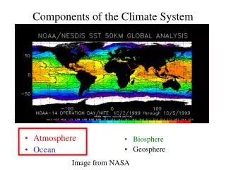
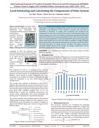
International Journal of Trend in Scientific Research and Development (IJTSRD) Volume 3 Issue 5, August 2019 Available Online: www.ijtsrd.com e-ISSN: 2456 – 6470 Load Estimating and Calculating the Components of Solar System Aye Myo Thant1, Thant Zaw Oo2, Ohmmar Myint3 1,2Department of Electrical Power Engineering,3Department of Engineering Mathematics 1Technological University, Mandalay, Myanmar 2,3Technological University, Kalay, Myanmar How to cite this paper: Aye Myo Thant | Thant Zaw Oo | Ohmmar Myint "Load Estimating and Components of Solar System" Published in International Journal of Trend in Scientific Research and Development (ijtsrd), ISSN: 2456- 6470, Volume-3 | Issue-5, August 2019, pp.213-217, https://doi.org/10.31142/ijtsrd25281 Copyright © 2019 by author(s) and International Journal of Trend in Scientific Research and Development Journal. This is an Open Access article distributed under the terms of the Creative Commons Attribution License (CC (http://creativecommons.org/licenses/by /4.0) The irradiance for AM 1.5 is accepted as the standard calibration spectrum for photovoltaic cells. Irradiation is the measure of energy density of sunlight and is measured in kWh/m2. Since energy is power integrated over time, irradiation is the integral of irradiance. Normally, the time frame for integration is one day, which means during daylight hours. ABSTRACT This paper is focused to develop solar system in rural area because the electricity is the backbone of the country’s economy and only 40% is electrified in Myanmar. In design load estimating and calculation the components for the solar system and moreover environmental impact and climate change is also a fact to consider in it. Myanmar has high solar potential, photovoltaic (PV) system must be installed for most of the rural areas where there is no national grid line. To develop off-grid PV system which support for people to lift up their lives in rural areas. Mono-crystalline or single crystalline silicon photovoltaic cells and lead acid batteries are going to use in the system. The load estimation, PV sizing, inverter selection and battery sizing are calculated mainly. Based on the results, the design consideration can be absolutely applicable for the one village. KEYWORDS: solar radiation, load estimation, solar system, charge controller, batteries capacities 1.INTRODUCTION The solar constant for the Earth is the irradiance received by the Earth from the sun at the top of the atmosphere, i.e., at AM 0, and is equal to 1367Wh/m2. After passing through the atmosphere with a path length of AM 1, the irradiance is reduced to approximately 1000Wh/m2, and has a modified spectral content due to atmospheric absorption. Calculating the IJTSRD25281 BY 4.0) The average solar radiation in Myanmar is more than 5 kWh/m2/day during the dry season. It varies from 2.3 to 3.2 kWh/m2/day in the extreme north and south regions, while the majority regions in Myanmar including the central area have good solar radiation ranging from 3.6 to 5.2 kWh/m2/day in figure (2). Therefore, government and private sector organizations have been promoting and piloting solar PV systems for rural electrification[3]. The specific monthly solar radiation profile for the selected village model is shown in Figure (1). The radiation is over 2000 Wh/m2. From this figure, the radiation is highest in April (6.422 kWh/m2/day) and is lowest in August (4.532 kWh/m2/day). Figure2. Monthly Solar Radiations of the Selected Village 2.Mathematical Review The necessary equations are considered for designing covered of solar system which is applied for a village. The angle formed between the plane of the equator and a line drawn from the center of the sun to the center of the earth is called the solar declination, δ. It varies between the extremes of ± 23.45°, and a simple sinusoidal relationship that assumes a 365 day per year and which puts the spring equinox on day n = 81 provides a very good approximation. ° = ) 81 - n ( 365 360 Equation (1) 23 . 45 sin δ Figure1. Model of Load Design for a Village @ IJTSRD | Unique Paper ID – IJTSRD25281 | Volume – 3 | Issue – 5 | July - August 2019 Page 213
International Journal of Trend in Scientific Research and Development (IJTSRD) @ www.ijtsrd.com eISSN: 2456-6470 where, δ = the angle between the plane of the equator and a line drawn from the center of the sun and center of the earth (varies between extremes of ± 23.45⁰) βN = altitude angle of the sun at noon L = latitude angle of the selected location βN = 90° − L + δ Equation (2) The tilt angle that would make the sun’s rays perpendicular to the module at noon would therefore be: Tilt angle of array, θ = 90° ̶ βN The average peak power, Pave,peak = kWh/day Equation (13) where, Tsh = the peak sun hours (hrs./day) The total dc current of the system, Idc = A Equation (14) The total number of modules, Ntotal = The number of modules in series, Equation (15) Total load demand (Wh /day) = Power in Watt × Hours in use Equation (3) Total load demand (Ah/day) = Total load (kWh/day) System Voltage Inverter efficiency × Equivalent sun hours is equal to total sum hours/365 days. System battery size can be calculated by using the following Equations. The required daily average energy demand has already been calculated. the required daily average energy demand, E rd Ns= Equation (16) The number of parallel modules strings, Np = Equation (4) Equation (17) Where, Vdc = the dc voltage of the system Vrm = the rated voltage of each module Irm = the rated current of each module The total number of modules, Ntotal= Ns× Np Equation (18) The output power of PV array = Ntotal× Power of one module Equation (19) And then, Array rated current = Np× Impp Equation (20) Array short-circuit current = Np×Isc Equation (21) Array rated voltage = Ns × Vmpp Equation (22) Array opened-circuit voltage = Ns× Voc Equation (23) Where, Isc = the short circuit current Imp = the current at maximum power point Vmp = the voltage at maximum power point Voc = the opened circuit voltage Minimum Controller Input Current, Isc,min = Np× Isc× safety factor Equation (24) This is the input current that comes from the solar array. The number of parallel strings in the array increases the current. To be on the safe side, it is advised to multiply the result by a safety factor of 1.25. 2.2.Determination of Cables Size The wiring must not reduce the performance of any of the components of the system. The cables in a mini grid connected system must be sized correctly to reduce the voltage drops in the cable and to make sure that the safe current handling capacity of the cable is not exceeded. The voltage drop in a cable is given as, ΔV= 2 (L× I × ρ) / A Equation (25) Erd = Equation (5) where, ηbat = the efficiency of the battery ηinv = the efficiency of the inverter ηc = the efficiency of the cables The estimate energy storage, Eest = Erd×the number of autonomy days Equation (6) The safe energy storage, energy estimate the storage, E sd Esafe= Equation (7) maximum depth of discharge , D dish The total capacity of battery bank in ampere-hours, Ctb storage, energy safe the E safe Ctb = Equation(8) voltage dc rated the of battery one , V b The total number of batteries, capacity total battery of bank Ahs Nt= Equation (9) battery one slected of capacity the The number of batteries in series, Nsb =Vdc/Vb Equation (10) The number of parallel batteries, Npb = Ntb/Nsb Equation (11) The total number of batteries, Ntb= Nsb× Npb Equation (12) 2.1.Determining the Sizing of PV Array System array size is essential for the calculation of standalone solar electricity generation system. The more there is system capacity, the more the module capacity is selected. @ IJTSRD | Unique Paper ID – IJTSRD25281 | Volume – 3 | Issue – 5 | July - August 2019 Page 214
International Journal of Trend in Scientific Research and Development (IJTSRD) @ www.ijtsrd.com eISSN: 2456-6470 where, ρ = the resistivity of copper wire which is normally taken to be 1.724 × 10⁻⁸ Ωm L = the length of cables in meters I = the current through the cables in amperes A = the cross-sectional area in mm2 The multiplication by 2 accounts for total circuit wire length. ΔV = Maximum cable voltage drop (5%) × system voltage Equation (26) In the design of the system, a maximum cable voltage drops of 5% was used that is why the maximum allowable drop in PV mini grid connected systems. 2.3.Considering System Voltage Total load demand (W/day) is divided by the system voltage. It is smaller less than 100A. Thus, Let system voltage be 12V, 18kW/day ÷ 12V = 1500A > 100A Let system voltage be 24V, 18kW/day ÷ 24V = 750A > 100A Let system voltage be 48V, 18kW/day ÷ 48V = 375A > 100A Let system voltage be 96V, 18kW/day ÷ 96V = 187A > 100A Let system voltage be 192V, 18kW/day ÷ 192V = 94A < 100A Therefore, system voltage 192V is chosen. 2.4.Calculating Inverter Size Inverter size is important = Maximum Peak Hour Demand * 1.25 = 55 kW * 1.25 = 68750 W Therefore, 70 kVA three phase inverter is chosen. Total load demand (Wh /day) = Power in Watt × Hours in use = 428 kWh Total load demand (Ah/day) Total load (kWh/day) System Voltage Inverter efficiency × = 2623 Ah/day Assuming; The efficiency of the inverter is 85%. 2.5.Considering System Losses The total loads plus the system losses (10%) = Total Estimated Load (Ah/day) + 10% = 2623 + 10% = 2885 Ah/day 2.6.Calculating the Solar Irradiation in Daily Equivalent Sun Hours Total sun hours = 2000kWhm-2/1000Wm-2 Total hours = 2000 hrs Therefore, Equivalent sun hours = 2000hrs/365days = 5.5 hrs/day 3.Consideration for Results The demand side has to size the load and calculate the daily energy consumption in kWh. The configuration for managing the total load consumption for the entire site is shown in table. which describes the total daily load demand for residence, communal facilities, and commercial facilities. The proposed area is a village as a sample selection, which is located in central Myanmar at 19.00⁰ Latitude and 95.00⁰ Longitude nearly. Most of the people in this village mainly depend on small patrol engine, batteries and some of people are using candle lamp for lighting, phone charger and other electricity appliances. Load profile is mainly divided into three portions that are residence, communal facilities and commercial facilities. In residence, there are many kinds of household level such as a high-income level, medium income level and low-income level respectively. Electricity demand in low income level is limited to lighting and TV, and the annual growth rate of electricity consumption is small. In such Medium household level, the annual growth rate of electricity consumption is rapidly increasing. It is considered the facts as shown in table 4. It is calculated in the whole in which system battery size; no of parallel batteries, battery capacity and data for PV array, Total Daily Demand Estimation for Proposed Village and Maximum Peak Hour Demand for Proposed Village. Maximum peak hour demand is 55kW/h, no of batteries are (12V 200Ah) (608) nos as shown in table (7). = Table2. Total Daily Demand Estimation for Proposed Village Types of Loads Daily Demands (Wh) Low-income Medium-income High-income School 1 School 2 Clinic Monastery 1 Monastery 2 Street Lights Total Daily Demand No. Remark 200 households 100 households 25 households 18 kW/day 177000 167800 61875 1179 683 2863 3286 2876 10800 1. Households 2. 3. 4. 5. 6. 7. 428362 Wh/day @ IJTSRD | Unique Paper ID – IJTSRD25281 | Volume – 3 | Issue – 5 | July - August 2019 Page 215
International Journal of Trend in Scientific Research and Development (IJTSRD) @ www.ijtsrd.com eISSN: 2456-6470 Table3. Maximum Peak Hour Demand for Proposed Village Types of Loads Peak Hour Demand (W/h) Low-income Medium-income High-income School 1 School 2 Clinic Monastery 1 Monastery 2 Street Lights Maximum Peak Hour Demand (W/h) No. Remark 200 households 100 households 25 households 7-10 pm 20000 30000 7500 175 130 1060 1200 1120 900 55000 W/h 1. Households 2. 3. 4. 5. 6. 7. Table4. Daily Load Estimation for Medium Income Households Type of Load Time of usage /day(h) Capacity of load (W) Daily usage (Wh) LCD/LED 4 Portable Player 2 LED bulb 22 Florescent Lamp 9 Street Light 11 Mobile Charger 6 Power Bank 2 Torch Light 1 DVD Player 4 Set-Top Box 4 Sound Box 2 Refrigerator 9 Total daily usage (Wh) Table5. Design Data for System Battery Size System battery capacity Number of parallel batteries Number of series batteries Total number of batteries Required battery Ah capacity 122687.5 Ah Allowable depth of discharge Max. efficiency Table6. Design Data for PV Array Model Number of parallel modules Number of series modules Total number of modules Array rated current Array short-circuit current Array rated voltage Array opened-circuit voltage Table7. Summarized Design Data of Proposed System Site name Site location Equivalent sun hour (ESH) Total daily demand Maximum peak hour demand System voltage Solar panel (24V 250W) Number of modules in series Number of parallel modules strings Battery (12V 200Ah) Number of batteries in series Number of batteries in parallel Charge Controller (MPPT) Inverter (Pure Sine Wave) 75 25 3 8 10 10 100 10 20 20 100 50 300 50 66 72 110 60 200 10 80 80 200 450 1678 200Ah, 12V 38 16 608 Nos 80% 95% 24V 250W PV Panel 55 8 440 Nos 436.7 A 478.5 A 252 V 302.4 V Central Myanmar 19.00 Latitude and 95.00° Longitude 5.5 hrs 18 kW 55000 W/h 192 V 440 nos 8 nos 55 nos 608 nos 16 nos 38 nos 600 A 70 kVA, 3 phases @ IJTSRD | Unique Paper ID – IJTSRD25281 | Volume – 3 | Issue – 5 | July - August 2019 Page 216
International Journal of Trend in Scientific Research and Development (IJTSRD) @ www.ijtsrd.com eISSN: 2456-6470 4.Conclusions This paper hope that to support the designed solar system for rural area development in which load demand and design focus components were expressed in detail. There are medium income households, monastery, clinic, school and street lights. Moreover the inverter type, PV array, Solar Irradiation in Daily Equivalent Sun Hours, system losses, system voltage and cable size is mainly considered. It will be useful for a village at central Myanmar inwhere 200 households are living in these areas. 5.Acknowledgements The author is deeply grateful to her teachers who are working in Electrical Power Engineering Department, Technological University (Mandalay) for their willingness to share of ideas and helpful suggestions on this paper writing. 6.References [1]Hla Myo Aung, Zaw Min Naing, Thi Thi Soe, “Status of Solar Energy Potential, Development and Application in Myanmar”. International Journal of Science and Engineering Applications, Vol 7-Issue 08,133-137, 2018. [2]Thet Thet Han Yee, Su Su Win, and Nyein Nyein Soe “Solar Energy Potential and Application in Myanmar”, International Journal of Humanities and Social Science, Vol:2, No.6, 2008 [3]Andrew Said, Matti Kummu, “Myanmar’s Renewable Energy Potential –Open source re-sources mapping for electrification of rural communities, Master Thesis, School of Engineering, Aalto University, Espoo 06.05.2018. [4]Noor Hussain Al Dulaimi *, Dr. Ammar Alkhalidi, “Design of an Off-Grid Solar PV System for a Rural Shelter”, Department of Energy Engineering, School of Natural Resources Engineering and Management, German Jordanian University,2016 [5]Soe Moe Aung, Prapita Thanarakb “Renewable energy potential and its utilization for rural electrification in Myanmar”, International Journal of Renewable Energy, Vol. 10, No. 1, January - June 2015 @ IJTSRD | Unique Paper ID – IJTSRD25281 | Volume – 3 | Issue – 5 | July - August 2019 Page 217