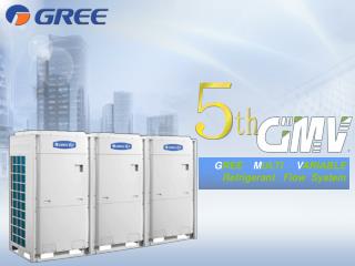
Variable Refrigerant Flow System
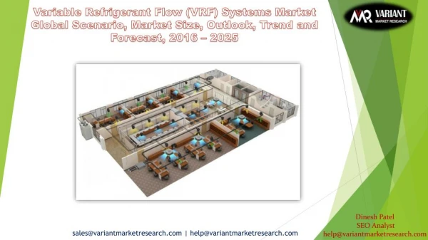
The heating, ventilation, and air conditioning HVAC system is arguably the foremost advanced system put in in an exceedingly building and is liable for a considerable part of the entire building energy use. Variable refrigerant flow is varied exploitation either and discoverer controlled variable speed mechanical device , or multiple mechanical device of varied capability in response to changes within the cooling heating needed within the air conditioned space. The variable refrigerant Flow VRF air conditioning system as a high degree of intellectual control, with every indoor unit being able to directly start the air conditioning system, freely setting and regulating the temperature, the volume and direction of the current ,and the mode. Every indoor unit can separately control it start and close, and regulate its operations. HVAC style involves quite simply the load estimate calculation the load calculation is that the start of the repetitious HVAC style procedure. This strategy guideline discusses the data required to style the air distribution system to deliver the right quantity of conditioned air to an area. Heating and cooling masses area unit dependent upon the building location, sighting, and therefore the construction of the house, whereas the instrumentation choice and therefore the air distribution style area unit dependent upon the loads and each other. The Variable refrigerant flow systems may be a particularly good option for buildings with multiple zones or wide variance heating cooling loads across many different internal zones. These systems provide individual control and the most versatile of the multi split systems. Hotels, school and office buildings are good examples. S. Visweswara Rao | K. Rajashekar | M. Sandeep | R. Dharmendar Kumar "Variable Refrigerant Flow System" Published in International Journal of Trend in Scientific Research and Development (ijtsrd), ISSN: 2456-6470, Volume-4 | Issue-1 , December 2019, URL: https://www.ijtsrd.com/papers/ijtsrd29566.pdf Paper URL: https://www.ijtsrd.com/engineering/mechanical-engineering/29566/variable-refrigerant-flow-system/s-visweswara-rao<br>

Variable Refrigerant Flow System
E N D
Presentation Transcript
International Journal of Trend in Scientific Research and Development (IJTSRD) Volume 4 Issue 1, December 2019 Available Online: www.ijtsrd.com e-ISSN: 2456 – 6470 Variable Refrigerant Flow System S. Visweswara Rao1, K. Rajashekar2, M. Sandeep2, R. Dharmendar Kumar2 1Assistant Professor, 2UG Scholar, 1,2Department of Mechanical Engineering, Guru Nanak Institute of Technology, Rangareddy, Telangana, India ABSTRACT The heating, ventilation, and air-conditioning (HVAC) system is arguably the foremost advanced system put in in an exceedingly building and is liable for a considerable part of the entire building energy use. Variable refrigerant flow is varied exploitation either and discoverer controlled variable speed mechanical device , or multiple mechanical device of varied capability in response to changes within the cooling heating needed within the air conditioned space. The variable refrigerant Flow (VRF) air conditioning system as a high degree of intellectual control, with every indoor unit being able to directly start the air conditioning system, freely setting and regulating the temperature, the volume and direction of the current ,and the mode. Every indoor unit can separately control it start and close, and regulate its operations. HVAC style involves quite simply the load estimate calculation the load calculation is that the start of the repetitious HVAC style procedure. This strategy guideline discusses the data required to style the air distribution system to deliver the right quantity of conditioned air to an area. Heating and cooling masses area unit dependent upon the building location, sighting, and therefore the construction of the house, whereas the instrumentation choice and therefore the air distribution style area unit dependent upon the loads and each other. The Variable refrigerant flow systems may be a particularly good option for buildings with multiple zones or wide variance heating/cooling loads across many different internal zones. These systems provide individual control and the most versatile of the multi-split systems. Hotels, school and office buildings are good examples. 1.INTRODUCTION Variable refrigerant flow (VRF) is associate air-condition system configuration wherever there's one out of doors compressing unit and multiple indoor units. The term variable refrigerant flow refers to the power of the system to manage the number of refrigerant flowing to the multiple evaporators (indoor units), sanctionative the utilization of many evaporators of differing capacities and configurations connected to one compressing unit. The arrangement provides associate individualized comfort management, and coinciding heating and cooling in numerous zones. Currently wide applied in massive buildings particularly in Japan and Europe, these systems area unit simply commencing to be introduced within the U.S. The VRF technology/system was developed and designed by Daikin Industries, Japan UN agency named and guarded the term variable refrigerant volume (VRV) system therefore different makers use the term VRF "variable refrigerant flow". In essence both are same. With the next potency and accrued controllability, the VRF system will facilitate accomplish a property style. Unfortunately, the look of VRF systems is additional difficult and needs further work compared to coming up with a standard direct growth (DX) system. This course provides an overview of VRF system technology. 2.LITERATURE SURVEY Mr. Johnathan wood VRF air-conditioning systems owe their growing popularity to their ability to meet a wide range How to cite this paper: S. Visweswara Rao | K. Rajashekar | M. Sandeep | R. Dharmendar Kumar "Variable Refrigerant Flow System" Published in International Journal of Trend in Scientific Research and Development (ijtsrd), ISSN: 2456-6470, Volume-4 | Issue-1, December 2019, https://www.ijtsrd.com/papers/ijtsrd29 566.pdf Copyright © 2019 by author(s) and International Journal of Trend in Scientific Research and Development Journal. This is an Open Access article distributed under the terms of the Creative Commons Attribution License (CC (http://creativecommons.org/licenses/by /4.0) IJTSRD29566 pp.446-450, URL: BY 4.0) of requirements, as Tony Nielsen explains. The primary function of all air-conditioning systems is to provide thermal comfort for building occupants. There is a wide range of system types available, staring with the basic window-fitted unit through to the very latest VRF (variable refrigerant flow) equipment. Deciding which system best suits the application will depend on several variables. For example, in a modern, design-conscious requirements of the client may prove of greater importance than the number of control options they provide. While a client looking for the best life-cycle cost will need to balance capital cost with long-term operating costs, efficiency and predicted VRF systems provide cooling and heating using refrigerant (R407C or R410A) as the working fluid. There are two basic types of VRF system cooling/heating-only and energy-recovery [1]. Tianzhen hong A VRF system's ability to control the refrigerant mass flow rate according to the cooling and/or heating load enables the use of as many as 60 indoor units with differing capacity 1989 2010 1989 2010 1989 2010 1989 2010 in conjunction with one single outdoor unit. This unlocks the possibility of having individualized comfort control, simultaneous heating and cooling in different zones, and heat recovery from one zone to another. The new VRF model in Energy Plus V8 developed by LBNL, was used for VRF system simulation in this study [2]. office the aesthetic @ IJTSRD | Unique Paper ID – IJTSRD29566 | Volume – 4 | Issue – 1 | November-December 2019 Page 446
International Journal of Trend in Scientific Research and Development (IJTSRD) @ www.ijtsrd.com eISSN: 2456-6470 Hussain shah Variable refrigerant flow (VRF) system is a mature heating, ventilation and air conditioning (HVAC) technology which simultaneously heat and cool area through extracting heat from an area which needs cooling and transfer heat to another area. Variable refrigerant flow (VRF) systems are installed with air conditioner inverter that adds a dc inverter which drives the control of compressor that modulates heat or cooling in the area. The compressor unit of variable refrigerant flow (VRF) are installed on the roof of the building, and heat & cool refrigerant are connected through piping connected to condition the building [3]. Rahul Dharia VRF (Variable Refrigerant Flow), sometimes known as variable refrigerant volume (VRV), is a smart climate control technology that offers high flexibility in terms of controlling temperature in different parts of a building at different times of a day. This innovative technology is becoming increasingly popular in large urban areas like Mumbai, Delhi, Kolkata, and Bangalore. VRF air conditioning systemis a highly popular AC type in the market today [4]. Rajkumar sundaram Variable refrigerant flow also known as VRV(variable refrigerant volume) Means the main compressor which pumps refrigerant around can run at various speeds (stepless) thereby has an ability to continuously increase (or decrease) flow of refrigerant based on demand during various hours/minutes of usage.(Most of basic traditional units, work only by start/stop of compressor. This means either 100% flow or 0% flow of refrigerant) [5]. Karthik Chandrasekaran Variable refrigerant flow, also known as VRV(variable refrigerant volume) Means the main compressor which pumps refrigerant around can run at various speeds Room thermal loads can go up or down gradually by suns heat or fluctuate rapidly when some doors are open/shut more often. Or sudden increase of rooms occupants. VRF Controls are designed to look at these fluctuations and adapt its cooling power almost like a automatic or CVT shift in a car [6]. 1.Heat Ventilation And Air- Conditioning Air conditioning is employed in most industrial properties, starting from little outlets and cafés to giant workplace buildings and public areas. To meet these numerous applications, air-con systems have totally different heating and cooling capacities and are available with varied setups and layouts. Many of our homes and most offices and commercial facilities would not become fordable without control of the indoor environment. The "luxury label" attached to air conditioning in earlier decades has given way to appreciate it practicality in making our live healthier and more productive. Along with speedy development in rising human comfort came the belief that product may well be created higher, faster, and a lot of economically during a properly controlled surroundings. AutoCAD is the AutoCAD software for mechanical, electrical, and plumbing designers and drafters. Creation and coordination of construction documents is more efficient with AutoCAD more intuitive systems drawing and design tools. AutoCAD additionally assessing our vision and enhance our potency attributable to its purposeful computer code for MEP designers and drafters. With AutoCAD we are able to make changes much faster, thus help minimizing the financial impact, and make those changes in almost real time. 1.2 History of HVAC In 1902, a twenty five – year – recent engineer from ny named Willis Carrier fictitious the primary trendy air – learning system. The mechanical unit, which sent air through water-cooled coils, was not aimed at human comfort, however; it was designed to control humidity in the printing plant where he worked. The first trendy electrical air-con unit was fictitious by Willis Carrier in 1902 in Buffalo, New York. After graduating from Cornell University, Carrier found a job at the Buffalo Forge Company. Heating, ventilation and air-con (HVAC) is that the technology of indoor and transport environmental comfort. Its goal is to supply thermal comfort and acceptable indoor air quality. Air conditioners use chemicals that simply convert from a gas to a liquid and back once more. This chemical is employed to transfer heat from the air within a home to the surface air. The machine has three main parts. They are a mechanical device, a condenser and an evaporator. HVAC Heating, Ventilating, and Air Conditioning (HVAC) equipment perform heating and/or cooling for residential, commercial or industrial buildings. The HVAC system might also be liable for providing recent outside air to dilute interior mobile contaminants like odors from occupants, volatile organic compounds (VOC’s) emitted from interior furnishings, chemicals used for cleaning, etc. A properly designed system can offer a snug indoor surroundings year spherical once properly maintained. 1.3 Working of Ac An air conditioning cools and dehumidifies the air as is passes over a chilly coil surface. The indoor coil is associate degree air-to-liquid device with rows of tubes that pass the liquid through the coil. Finned surfaces connected to those tubes increase the general area of the cold surface thereby increasing the warmth transfer characteristics between the air passing over the coil and liquid passing through the coil. The type of liquid used depends on the system designated. Direct-expansion (DX) instrumentality uses refrigerant because the liquid medium. Chilled-water (CW) may also be used as a liquid medium. When the specified temperature of a relaxing water system is close to the temperature of water, freeze protection is added in the form of glycols or salts. Regardless of the liquid medium used, the liquid is delivered to the cooling coil at a cold temperature. In the case of direct enlargement instrumentality, the air passing over the indoor cooling coil heats the cold liquid refrigerant. Heating the refrigerant causes boiling and transforms the refrigerant from a chilly liquid to a heat gas. This heat gas (or vapor) is tense from the cooling coil to the mechanical device through a copper tube (suction line to the compressor) wherever the nice and cozy gas is compressed. In some cases, associate degree accumulator is placed between the cooling coil and also the mechanical device to @ IJTSRD | Unique Paper ID – IJTSRD29566 | Volume – 4 | Issue – 1 | November-December 2019 Page 447
International Journal of Trend in Scientific Research and Development (IJTSRD) @ www.ijtsrd.com eISSN: 2456-6470 capture unused liquid refrigerant and ensures that solely vapor enters the mechanical device. The compression process increases the pressure of the refrigerant vapor and significantly increases the temperature of the vapor. The mechanical device pumps the vapor through another device (outdoor condenser) wherever heat is rejected and also the hot gas is condensed to a heat high liquid. This heat high liquid is tense through a smaller copper tube (liquid line) to a filter (or filter/dryer) and so on to associate degree enlargement device wherever the high pressure liquid is reduced to a chilly, low liquid. The cold liquid enters the indoor cooling coil and also the method repeats. 1.4 Importance of HVAC HVAC is a vital a part of residential structures like single family homes, apartment buildings, hotels and senior living facilities, medium to large industrial and office buildings such as skyscrapers and hospitals, onboard vessels, and in marine environments, where safe and healthy building conditions are regulated with respect to temperature and humidity, using fresh air from outdoors. Ventilation is that the method of exchanging or substitution air in any area to supply high indoor air quality that involves temperature management, oxygen replenishment, and removal of moisture, odors, smoke, heat, dust, mobile bacterium, carbon dioxide, and other gases. 1.5 Types of Air Conditioning Systems A.Window Air Conditioner. B.Split Air Conditioner. C.Packaged Air Conditioner. D.Central Air Conditioning System. E.VRV, VRF air Conditioning System. 1.5.1 Window Air Conditioner Window air conditioning is that the most typically used air conditioning for single rooms. In this air conditioning all the parts, namely the compressor, condenser, expansion valve, evaporator and cooling coil are enclosed in a single box. This unit is fitted during a slot created within the wall of the space, or a lot of usually a window sill. this unit you don’t need to build any make time for the wall of the space. Further, gift day split units have aesthetic attractiveness and don't take up the maximum amount house as a window unit. A split cooling system are often wont to cool one or 2 rooms. Figure1.2 Split air conditioning system 1.5.3 An HVAC designer can counsel this kind of cooling system if you would like to cool down over 2 rooms or a bigger house at your home or workplace. There square measure 2 potential arrangements with the package unit. In the initial one, all the parts, specifically the mechanical device, condenser (which can be air cooled or water cooled), expansion valve and evaporator are housed in a single box. The cooled air is thrown by the high capacity blower, and it flows through the ducts laid through various rooms. In the second arrangement, the mechanical device and condenser square measure housed in one casing. The gas passes through individual units, comprised of the enlargement valve and cooling coil, situated in numerous rooms. Packaged Air Conditioner Figure 1.3 Packaged Air Conditioning Unit 1.5.4 Central air con is employed for cooling huge buildings, houses, offices, entire hotels, gyms, movie theaters, factories etc. If the entire building is to be air conditioned, HVAC engineers find that putting individual units in each of the rooms is very expensive making this a better option. A central air con system is comprised of a large mechanical device that has the capability to provide many loads of air con. Cooling huge halls, malls, Brobdingnagian areas, galleries etc is sometimes solely possible with central acquisition units. 1.6 Refrigerant A refrigerant may be a substance or mixture, sometimes a fluid, utilized in a setup and refrigeration cycle. Refrigeration may be a method of moving heat from one location to a different in controlled conditions. The work of warmth transport is historically driven by mechanical work, but can also be driven by heat, magnetism, electricity, laser, or other means. Central Air Conditioning System Figure1.1 Window air conditioning system 1.5.2 The split cooling system includes of 2 elements the outside unit and also the indoor unit. The outside unit, fitted outside the space, homes parts just like the mechanical device, condenser and enlargement valve. The indoor unit includes the evaporator or cooling coil and also the cooling fan. For Split Air Conditioner @ IJTSRD | Unique Paper ID – IJTSRD29566 | Volume – 4 | Issue – 1 | November-December 2019 Page 448
International Journal of Trend in Scientific Research and Development (IJTSRD) @ www.ijtsrd.com eISSN: 2456-6470 In most cycles it undergoes part transitions from a liquid to a gas and back once more. Many operating fluids are used for such functions. Fluorocarbons, especially chlorofluorocarbons, became commonplace in the 20th century, gerents used in various applications are ammonia, sulfur dioxide, and non- halogenated but they are being phased out because of their ozone depletion effects. Other common refry hydrocarbons such as propane. 1.6.1 Types Of Refrigerants The most common types of refrigerants in use nowadays are presented below ?Halocarbons ?Isotropic refrigerants. ?Zoetrope refrigerants. ?Inorganic refrigerants like carbon dioxide, ammonia, water and air. ?Hydrocarbon refrigerants. ?Halocarbons are generally synthetically produced. Depending on whether they include chemical elements hydrogen (H), carbon (C), chlorine (Cl) and florine (F) they are named after as follows: ?CFCs (Chlorofluorocarbons):R11, R12, R113, R114, R115 ?HCFCs (Hydro chlorofluorocarbons): R22, R123 ?HFCs (Hydro fluorocarbons): R134a, R404a, R407C, and R410a 1.7 Various Lines and Curves In Psychrometric Chart All the properties of air indicated in the psychometric chart are calculated at the standard atmospheric pressure. For alternative pressures relevant corrections got to be applied. The psychometric chart looks like a shoe. The various lines shown within the chart ar as follows. Dry Bulb (DB) Temperature Lines The dry bulb metric is shown on the bottom of the shoe formed psychology chart forming the only. The decibel temperature will increase from the left to the correct. The vertical lines shown within the chart ar the constant decibel temperature lines and every one the points placed on a selected vertical line have same decibel temperature. Wet Bulb (WB) Temperature Lines The outer curve on the left facet indicates the Wet Bulb (WB) metric. The constant temperature lines ar the diagonal lines extending from Wb temperature sinuous scale downwardly towards the correct hand facet of the chart. All the points placed on the constant Wb temperature line have an equivalent temperature. Relative humidity The ratio of the vapour pressure of moisture in the sample to the saturation pressure at the dry bulb temperature of the sample. Dew Point (DP) Temperature Lines Since the temperature temperature of the air depends on the wetness content of the air, constant moisture lines are also constant DP temperature lines. The scale of the refugee and Wb temperature is that the same, however, whereas the constant Wb temperature lines ar diagonal lines extending downwardly, the constant DP temperature lines are horizontal lines. Thus the constant refugee and Wb temperature lines ar completely different. Humidity Ratio These are the horizontal lines on the chart. Humidity magnitude relation is typically expressed as mass of wetness per mass of dry air (pounds or metric weight units of wetness per pound or kilogram of dry air, respectively). The range is from 0 for dry air up to 0.03 (blew/lamb) on the right hand ω-axis, the ordinate or vertical axis of the chart. 1.8 Duct System Ducts ar conduits or passages utilized in heating, ventilation, and air conditioning (HVAC) to deliver and remove air. The required airflows embody, for instance, supply air, return air, and exhaust air. Ducts normally conjointly deliver ventilation air as a part of the provision air. As such, air ducts ar one methodology of making certain acceptable indoor air quality in addition as thermal comfort. Process duct work conveys giant volumes of hot, dust- covered air from process instrumentality to mills, bughouses to alternative method instrumentality. Process duct work may be round or rectangular. Although round duct work costs more to fabricate than rectangular duct work, it requires fewer stiffeners and is favored in many applications over rectangular ductwork. The air in method duct work could also be at close conditions or might operate at up to 900 °F (482 °C). Process ductwork varies in size from two linear unit diameter twenty|to twenty} linear unit diameter or to maybe 20 linear unit by forty linear unit rectangular. Large method ductwork might fill with dirt, depending on slope, to up to 30% of cross section, which can weigh 2 to 4 tons per linear foot. Round ductwork is subject to duct suction collapse, and requires stiffeners to minimize this. But is additional economical on material than rectangular duct work. 1.9 Variable Refrigerant Flow (VRF) Systems Variable refrigerant flow (VRF) is associate air-condition system configuration wherever there's one outside condensation unit and multiple indoor units. The term variable refrigerant flow refers to the power of the system to manage the quantity of refrigerant flowing to the multiple evaporators (indoor units), facultative the utilization of many evaporators of differing capacities and configurations connected to one condensation unit. The arrangement provides associate individualised comfort management, and concurrent heating and cooling in several zones. Currently wide applied in massive buildings particularly in Japan and Europe, these systems square measure simply commencing to be introduced within the U.S. The VRF technology/system was developed and designed by Daikin Industries, Japan World Health Organization named and guarded the term variable refrigerant volume (VRV) system thus different makers use the term VRF "variable refrigerant flow". In essence both are same. With a better potency and augmented controllability, the VRF system will facilitate attain a property style. Unfortunately, the planning of VRF systems is additional difficult and needs extra work compared to coming up with a @ IJTSRD | Unique Paper ID – IJTSRD29566 | Volume – 4 | Issue – 1 | November-December 2019 Page 449
International Journal of Trend in Scientific Research and Development (IJTSRD) @ www.ijtsrd.com eISSN: 2456-6470 traditional direct enlargement (DX) system. This course provides an outline of VRF system technology. 1.10Types of VRF ?VRF heat pump systems ?Heat Recovery VRF system ?VRF Water Cooled ?Gas Driven 1.10.1 VRF heat pump systems VRF apparatus systems ordinarily called a pair of pipe, allow heating or cooling altogether of the indoor units however NOT concurrent heating and cooling. When the indoor units square measure within the cooling mode, they act as evaporators; once they square measure within the heating mode, they act as condensers. VRF apparatus systems square measure effectively applied in open set up areas, retail stores, cellular offices and the other space that need cooling or heating throughout identical operational periods. 1.10.3 VRF Water Cooled Most commonly used square measure cool systems, using packaged outdoor condensing units, which via refrigeration pipe work connect to a number of indoor units. There are however some limitations, pipe work runs, mainly vertical risers (although Samsung can have a vertical rise up to 115mtere), plant space and noise. Where these become a difficulty then water cooled systems may be used. They operate as the Air-cooled units, but instead of having a built in air cooled heat exchanger they utilise and plate heat exchanger, which transfers the energy into a water loop. This is connected to a cooling system or dry cooler that transfers the energy/ heat to atmosphere. Due to this method the water cooled VRF systems may be placed internally with no worry concerning the vertical risers, in abundant smaller areas, seizing less area and can be attenuated to meet most environmental requirements. These systems are also ideal for building served by an existing landlords condenser water loop. CONCLUSION The variable refrigerant flow system is taken into account to be one amongst the foremost promising energy saving technologies gaining its momentum in recent year. A variable energy efficient technology is needed to conserve energy as well as to achieve better human comfort. So this is been new and efficient way to design HVAC system with VRF technology. It provides realistic choice to traditional central systems. Its brings a number of the most recent technology to the market and provides the next degree of responsibility, comfort and energy potency that's expected from today’s shopper. REFERENCES [1]Mr. Johnathan wood VRF air-conditioning systems Dynamic Simulation of Energy Management Control Functions for HVAC Systems in Buildings, Energy Conversion and Management 47 (7–8), 926-943. Figure 1.7 VRF heat pump system 1.10.2 Heat Recovery VRF system Variable refrigerant flow systems with heat recovery (VRF- HR) capability will operate at the same time in heating and/or cooling mode, facultative heat to be used instead of rejected because it would be in traditional heat pump systems. Each indoor unit is branched off from the 3 pipes using solenoid box which contains a series of valves. An indoor unit requiring cooling can open its liquid line associated suction line valves and act as an evaporator. An indoor unit requiring heating can open its hot gas and liquid line valves and can act as a condenser. Typically, further heat exchangers in distribution boxes square measure accustomed transfer some reject heat from the superheated refrigerant exiting the zone being cooled to the refrigerant that's going to the zone to be heated. This reconciliation act has the potential to supply vital energy savings 3 pipe apparatus systems square measure effectively applied in open set up areas, retail stores, cellular offices and any other space that need cooling and heating at identical time. [2]Tianzhen hongInternational Energy Agency (IEA), World Energy Outlook, OECD/IEA, France, 2012. www.worldenergyoutlook.org/publications/weo2012. [3]Hussain shah Heating and Cooling Energy Trends and Drivers in Buildings, Renewable and Sustainable Energy Reviews 41, 85-98. [4]Rahul Dharia Variable Refrigerant Flow Systems, ASHRAE Journal 49 (4), 24-31. [5]Rajkumar sundaram Experimental Evaluation of the Ventilation Effect on the Performance of a VRV System in Cooling Mode-Part I: Experimental evaluation, HVAC&R Research, Vol.14, No.4, 615-630. [6]Karthik Chandrasekaran Simulation Evaluation of the Ventilation Effect on the Performance of a VRV System in Cooling Mode—Part II: Simulation Evaluation. HVAC&R Research, Vol. 14, No. 5, 783-795. Figure1.8 Heat recovery VRF system @ IJTSRD | Unique Paper ID – IJTSRD29566 | Volume – 4 | Issue – 1 | November-December 2019 Page 450