Download
1 / 7
70 likes | 83 Vues
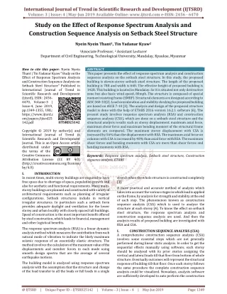
This paper presents the effect of response spectrum analysis and construction sequence analysis on the setback steel structure. In this study, the proposed building is eleven storey setback steel structure. The length of the proposed building is 78ft and width is 66ft. The effective height of proposed building is 142ft. This building is located in Mandalay. So it is situated not only destructive zone but also basic wind speed, 80mph. The structure is composed of special moment resisting frame SMRF . Structural elements are designed according to AISC 360 10 2 . Load consideration and stability checking for proposed building are based on ASCE 7 10 3 . The analysis and design of the proposed structure model is done with the help of ETABS 2016 version 16.2.1 software 6 . The present study involves response spectrum analysis RSA and construction sequence analysis CSA , which are done on a setback steel structure and the structural analysis results such as storey displacement, maximum axial force, maximum shear force and maximum bending moment of the structural frame elements are compared. The maximum storey displacement with CSA is increased by 56 than the displacement with RSA. The maximum axial force on columns with CSA is increased by 48 than axial force with RSA. The maximum shear forces and bending moments with CSA are more than shear forces and bending moments with RSA. Nyein Nyein Thant | Tin Yadanar Kyaw "Study on the Effect of Response Spectrum Analysis and Construction Sequence Analysis on Setback Steel Structure" Published in International Journal of Trend in Scientific Research and Development (ijtsrd), ISSN: 2456-6470, Volume-3 | Issue-4 , June 2019, URL: https://www.ijtsrd.com/papers/ijtsrd25142.pdf Paper URL: https://www.ijtsrd.com/engineering/civil-engineering/25142/study-on-the-effect-of-response-spectrum-analysis-and-construction-sequence-analysis-on-setback-steel-structure/nyein-nyein-thant<br>

E N D
International Journal of Trend in Scientific Research and Development (IJTSRD) Volume: 3 | Issue: 4 | May-Jun 2019 Available Online: www.ijtsrd.com e-ISSN: 2456 - 6470 Study on the Effect of Response Spectrum Analysis and Construction Sequence Analysis on Setback Steel Structure Nyein Nyein Thant1, Tin Yadanar Kyaw2 1Associate Professor, 2Assistant Lecturer Department of Civil Engineering, Technological University, Mandalay,Kyaukse, Myanmar How to cite this paper: Nyein Nyein Thant | Tin Yadanar Kyaw "Study on the Effect of Response Spectrum Analysis and Construction Sequence Analysis on Setback Steel Structure" Published in International Journal of Trend in Scientific Research and Development (ijtsrd), ISSN: 2456- 6470, Volume-3 | Issue-4, June 2019, pp.1349-1355, URL: https://www.ijtsrd.c om/papers/ijtsrd25 142.pdf Copyright © 2019 by author(s) and International Journal of Trend in Scientific Research and Development Journal. This is an Open Access article distributed under the terms of the Creative Commons Attribution License (CC BY 4.0) (http://creativecommons.org/licenses/ by/4.0) I. INTRODUCTION In recent times, multi-storey buildings are required to have free space due to shortage of space, population growth and also for aesthetic and functional requirements. Many multi- storey buildings are planned and constructed with variety of architectural requirements such as planning of irregular configurations. Setback structures include in vertical irregular structures. In particulars such a setback form provides adequate daylight and ventilation for the lower storey and urban locality with closely spaced tall buildings. Speed of construction is the most important benefit offered by steel construction, which leads to financial, management and other logistical benefits. ABSTRACT This paper presents the effect of response spectrum analysis and construction sequence analysis on the setback steel structure. In this study, the proposed building is eleven-storey setback steel structure. The length of the proposed building is 78ft and width is 66ft. The effective height of proposed building is 142ft. This building is located in Mandalay. So it is situated not only destructive zone but also basic wind speed, 80mph. The structure is composed of special moment resisting frame (SMRF). Structural elements are designed according to AISC 360-10[2]. Load consideration and stability checking for proposed building are based on ASCE 7-10 [3]. The analysis and design of the proposed structure model is done with the help of ETABS 2016 version 16.2.1 software [6]. The present study involves response spectrum analysis (RSA) and construction sequence analysis (CSA), which are done on a setback steel structure and the structural analysis results such as storey displacement, maximum axial force, maximum shear force and maximum bending moment of the structural frame elements are compared. The maximum storey displacement with CSA is increased by 56% than the displacement with RSA. The maximum axial force on columns with CSA is increased by 48% than axial force with RSA. The maximum shear forces and bending moments with CSA are more than shear forces and bending moments with RSA. Keywords: Response spectrum analysis, Setback steel structure, Construction sequence analysis, ETABS IJTSRD25142 stretch when the whole structure is constructed completely [1]. A more practical and accurate method of analysis which takes into account the various stages in which load is applied on the frame, by analysis for strength and stability at the end of each step. The phenomenon known as construction sequence analysis (CSA) which is used to analyse the structure at each storey [4]. To know the effect on setback steel structure, the response spectrum analysis and construction sequence analysis are used. And then the analysis results of proposed building are investigated with RSA and CSA. I. CONSTRUCTION SEQUENCE ANALYSIS (CSA) A comprehensive construction sequence analysis (CSA) involves some essential steps which are not generally performed during linear static analysis. In order to get the sequential effects manually using software, each storey should be analysed with its prior stories assigning the vertical and lateral loads till that floor from bottom of whole structure. Eventually outcomes will represent the structural response of building till that floor. Once each storey follows the same procedure the complete construction sequence analysis could be visualized. Nowadays, analysis software are sufficiently developed to auto perform the construction The response spectrum analysis (RSA) is a linear dynamic analysis method which measures the contribution from each natural mode of vibration to indicate the likely maximum seismic response of an essentially elastic structure. The method involves the calculation of the maximum value of the displacements and member forces in each mode using smooth design spectra that are the average of several earthquake motions. The building model is analysed using response spectrum analysis with the assumption that the structure and change of the load transfer to all the loads or full loads in a single @ IJTSRD | Unique Paper ID – IJTSRD25142 | Volume – 3 | Issue – 4 | May-Jun 2019 Page: 1349
International Journal of Trend in Scientific Research and Development (IJTSRD) @ www.ijtsrd.com eISSN: 2456-6470 sequence analysis easily. After grouping the software eventually ask for which facility should be taken and then the outcomes could be comparing among different conditions [5]. Stage formation in construction sequence analysis is shown in Figure 1. Exposure type Basic wind speed Topographic factor, Kzt Gust-effect factor, G Wind Important factor, I (4) Earthquake Load Seismic zone Occupancy category Spectral response acceleration (0.2s), Ss = 2.01 Spectral response acceleration (1.0s), S1 = 0.8 Seismic important factor, I Soil profile type Response modification coefficient, R System over strength factor, Ωo Deflection amplification factor, Cd (5)Load Combinations The designed load combinations are considered according to AISC 360-10 and ASCE 7-10. 1.1.4DL + 1.4SD 2.1.2DL + 1.2SD + LL 3.1.2DL + 1.2SD + 1.6LL 4.1.2DL + 1.2SD + LL + WX 5.1.2DL + 1.2SD + LL – WX 6.1.2DL + 1.2SD + LL + WY 7.1.2DL + 1.2SD + LL – WY 8.1.2DL + 1.2SD + 0.5WX 9.1.2DL + 1.2SD – 0.5WX 10.1.2DL + 1.2SD + 0.5WY 11.1.2DL + 1.2SD – 0.5WY 12.0.9DL + 0.9SD + WX 13.0.9DL + 0.9SD – WX 14.0.9DL + 0.9SD + WY 15.0.9DL + 0.9SD – WY 16.1.2DL + 1.2SD + LL + SPECX 17.1.2DL + 1.2SD + LL – SPECX 18.1.2DL + 1.2SD + LL + SPECY 19.1.2DL + 1.2SD + LL – SPECY 20.0.9DL + 0.9SD + SPECX 21.0.9DL + 0.9SD – SPECX 22.0.9DL + 0.9SD + SPECY 23.0.9DL + 0.9SD – SPECY Figure 2 and Figure 3 show floor plan and 3D view of the proposed building respectively. = B = 80 mph = 0.85 = 0.85 = 1.0 = V = II = 1.0 = SD = 8 = 3 = 5.5 Figure 1. Stage Formation in Construction Sequence Analysis (CSA) II. To analyse and design the proposed building, the required data such as site location, structural system, material properties and loading considerations are collected as follows. A.Site Location and Structural System The function of the proposed building is eleven-storey setback steel structure (hotel building). The proposed building exists in Mandalay. The maximum dimension is 66ft in X-direction and 78ft in Y-direction. The effective height of the structure is 142ft. The structure is composed of special moment resisting frame (SMRF). B.Material Properties The strength of a structure must be adequate to resist the applied loads and the strength of material depends on the type of material used. So, the material properties for structural data are as followed. Analysis property data Weight per unit volume of steel Modulus of elasticity, Es Poisson’s ratio, µ Coefficient of thermal expansion Design property data Yield strength of structural steel, Fy Ultimate strength of structural steel, Fu = 65 ksi C.Loading Considerations The applied loads are gravity loads and lateral loads. Gravity loads include dead loads, superimposed dead loads and live loads. Lateral loads of wind load and earthquake load are considered according to ASCE 7-10. (1) Dead Load 9 inches thick brick wall weight 4.5 inches thick brick wall weight Weight of finishing Weight of ceiling Slab ( 6'' thick) (2) Live Load Live load on private rooms & corridors serving private area Live load on assembly rooms & corridors serving public area Live load on stair Live load on flat roof Weight of lift Unit weight of water (3) Wind Load DATA PREPARATION FOR PROPOSED BUILDING = 490 pcf = 29000 ksi = 0.3 == 6.5 × 10⁻⁶ in/ in /° F = 50 ksi = 100 psf = 55 psf = 15 psf = 10 psf = Deck slab = 40 psf = 100 psf = 100 psf = 20 psf = 3 tons = 62.4 pcf Figure 2. Floor Plan of Proposed Building @ IJTSRD | Unique Paper ID – IJTSRD25142 | Volume – 3 | Issue – 4 | May-Jun 2019 Page: 1350
International Journal of Trend in Scientific Research and Development (IJTSRD) @ www.ijtsrd.com eISSN: 2456-6470 Figure 5. Column Layout Plan for 1F to 3F Figure 3. 3D View of Proposed Building ANALYSIS AND DESIGN RESULTS OF PROPOSED BUILDING WITH RSA Firstly, the proposed building is analysed and design for the load considerations and static load combinations. After the structural stability checking of the proposed building is done for linear static analysis, RSA is considered with gravity loads and lateral loads. A.Design Sections of Proposed Building In this study, the sections of beams W10x54, W14x53, W14x68 and W14x132 are used in proposed building. The sections of columns W14x132, W14x159, W14x176, W14x193, W14x211 and W14x233 are used in proposed building. Design results for frame elements are shown in Tables 1 and 2 respectively. For the proposed building, Figure 4 shows beam layout plan and the column layout plans are shown in Figure 5, Figure 6, Figure 7 and Figure 8. Figure 4. Beam Layout Plan for Proposed Building III. Figure 6. Column Layout Plan for 4F Figure 4. Beam Layout Plan for Proposed Building Figure 7. Column Layout Plan for 5F to 7F @ IJTSRD | Unique Paper ID – IJTSRD25142 | Volume – 3 | Issue – 4 | May-Jun 2019 Page: 1351
International Journal of Trend in Scientific Research and Development (IJTSRD) @ www.ijtsrd.com eISSN: 2456-6470 building is done for RSA, CSA is considered with gravity loads and lateral loads to know the effect of CSA on setback steel structure. Design sections of column and beam from CSA are not changed that obtained from RSA. IV. COMPARATIVE RESULTS OF RSA AND CSA To understand the effect of RSA and CSA on the setback steel structure, the structural responses such as storey displacement and internal forces on selected frame members are compared. Selected columns and beams are shown in Figure 9. Figure 8. Column Layout Plan for 8F to 10F TABLE I: COLUMN SIZES OF THE PROPOSED BUILDING Size Columns Types Storey Level (in x lb/ft) W 14x132 W 14x159 W 14x176 W 14x193 W 14x211 W 14x233 C1 C2 C3 C4 C5 C6 4F and RF 1F to 3F 8F to 10F 5F to RF 5F to 9F RF 1F to 10F 1F to 3F Figure 9. Selected Columns and Beams Location A.Comparison of Storey Displacement To know the structural responses due to RSA and CSA of setback steel structure with respect to floor level are compared. The comparative results in X and Y directions are illustrated in Figure 10 and Figure11. Table II: Beam Sizes Of The Proposed Building BeamTypes Storey Level B1 Landing Beam B2 All storey B3 All storey B4 All storey Size (in x lb/ft) W 10x54 W 14x53 W 14x68 W 14x132 B. The structural stability checking for the proposed building is considered according to ASCE 7-10. Five types of structural stability checking are overturning moment, sliding, torsional irregularity, storey drift and P-delta [3]. Table 3 shows the stability checking for proposed building. TABLE III: CHECKING FOR STABILITY OF THE PROPOSED BUILDING Checking Item direction direction Overturning Moment Sliding 4.12 Torsional Irregularity Storey Drift 2.064 in 1.194 in P-delta 0.010 In both X and Y directions, the safety factors of overturning moment, sliding, torsional irregularity, storey drift and P- delta checking for the building are within limitations. Therefore, the proposed building is satisfied according to the stability checking. C.Analysis and Design of CSA After the structural stability checking of the proposed Stability Checking X Y- Remark Limit Figure 10. Storey Displacement for X-direction with RSA & CSA OK 6.57 5.62 ≥ 1.5 OK 3.22 ≥ 1.5 1.009 OK 1.16 ≤ 1.2 OK OK ≤ 2.88 ≤ 0.1 0.005 Figure 11. Storey Displacement for Y-direction with RSA & CSA @ IJTSRD | Unique Paper ID – IJTSRD25142 | Volume – 3 | Issue – 4 | May-Jun 2019 Page: 1352
International Journal of Trend in Scientific Research and Development (IJTSRD) @ www.ijtsrd.com eISSN: 2456-6470 The maximum value of storey displacement is found at roof floor level with both RSA and CSA. The storey displacement in X-direction with CSA is increased by 49% than displacement with RSA. It can be seen that the storey displacement in Y-direction is smaller than that of X- direction due to both RSA and CSA because the proposed building is setback in Y-direction. B. Comparison of Axial Force on Columns The columns C45, C33, C23 and C43 are selected for comparison of axial forces with RSA and CSA. The selected columns C45 and C33 locate at the level of continuity of the proposed building. The selected columns C23 and C43 are located at the level of discontinuity of the proposed building. The comparison results are shown in Figure 12 to Figure 15. Figure 15. Axial Force for C43 with RSA & CSA The axial force for C23 with CSA is increased by 48% than axial force with RSA. The result of axial force for C43 with CSA is increased by 33% than axial force with RSA. Above comparison, the difference of axial forces with RSA and CSA is significantly increased at the selected exterior columns C45, C23 and C43. B. Comparison of Shear Force in Beams To understand the internal forces in selected beams due to RSA and CSA of setback steel structure are compared. The beams B80, B59, B45, B78 and B73 are selected for comparison of shear forces. Comparative results of selected beams are illustrated in Figure 16 to Figure 20. Figure 12. Axial Force for C45 with RSA & CSA Figure 13. Axial Force for C33 with RSA & CSA Figure 16. Shear Force for B80 with RSA & CSA The axial forces of C45 and C33 are maximum values at first floor with RSA and CSA. The axial force values obtained for C45 with CSA is increased by 22% than axial force with RSA. The axial force values obtained for C33 with CSA is increased by 6% than axial force with RSA. Figure 17. Shear Force for B59 with RSA & CSA The shear force value obtained for B80 and B59 with CSA is increased by 46% and 32% than shear force with RSA respectively. Figure 14. Axial Force for C23 with RSA & CSA @ IJTSRD | Unique Paper ID – IJTSRD25142 | Volume – 3 | Issue – 4 | May-Jun 2019 Page: 1353
International Journal of Trend in Scientific Research and Development (IJTSRD) @ www.ijtsrd.com eISSN: 2456-6470 Figure 18. Shear Force for B45 with RSA & CSA Figure 21. Bending Moment for B80 with RSA & CSA Figure 22. Bending Moment for B59 with RSA & CSA Figure 19. Shear Force for B78 with RSA & CSA The bending moment value obtained for B80 with CSA is increased by 37% than bending moment with RSA. Bending moment for B59 with CSA is increased in 43% of RSA. Figure 20. Shear Force for B73 with RSA & CSA The shear force for B45 with CSA is increased by 16.2% than shear force with RSA. Shear force for B78 with CSA is increased by 64% than shear force with RSA. Shear force of B73 with CSA is increased by 52% than shear force with RSA. The difference values of shear forces in selected beams B78, B73, B80 due to RSA and CSA are nearly about 50% since these selected beams are located at setback in Y-direction. The maximum shear force is found at the first floor and minimum value is at the roof floor for selected beams. The shear forces for selected beams are significantly decreased at the level of discontinuity of the proposed building. The value of shear forces for all selected beams with CSA is larger than RSA. D. Comparison of Bending Moment in Beams To know the internal forces in selected beams due to RSA and CSA of setback steel structure are compared. The comparisons of bending moments in selected beams are shown in Figure 21 to Figure 25. Figure 23. Bending Moment for B45 with RSA & CSA Figure 24. Bending Moment for B78 with RSA & CSA @ IJTSRD | Unique Paper ID – IJTSRD25142 | Volume – 3 | Issue – 4 | May-Jun 2019 Page: 1354
International Journal of Trend in Scientific Research and Development (IJTSRD) @ www.ijtsrd.com eISSN: 2456-6470 Figure 25. Bending Moment for B73 with RSA & CSA ACKNOWLEDGMENT The author offers her special thanks to Dr.Sint Soe, Rector and Dr.Yan Aung Oo, Pro-Rector, Technological University (Mandalay). The author would like to express heart-felt gratitude to Dr.Thazin Thein, Professor and Head of Civil Engineering Department, (Mandalay). The author is very thankful to Daw Nyein ein Thant, Associate Professor, and Department of Civil Engineering, Technological University (Mandalay), for her guidance, suggestions and necessary dvices. The author likes to express her thanks to all the teachers from the Department of Civil Engineering, Technological University (Mandalay), for their effective guidance and suggestion. The authorwishes to express specially thanks to Daw San San Myint , Associate Professor, and Department of Civil Engineering, Technological University (Mandalay), for her valuable advice, comments and special interest to be perfect this paper. Finally, the author’s special thanks are sent to her parents, for their supports and encouragement to attain her destination. REFERENCES [1]Vignesh Kini K, Rajeeva S V: “Comparison of Response Spectrum Analysis and Construction Sequence Analysis of RC and Steel-concrete Composite Multi-storey Building with Floating Columns”. International Journal of Research in Engineering and Technology Volume 6, Issue.05, May, 2017. Technological University The result of bending moment for B45 with CSA is increased by 40% than bending moment with RSA. The bending moment values obtained for B78 with CSA is increased by 54% than bending moment with RSA. Selected beam B73 of the bending moment with CSA is nearly two times as large as RSA. The difference values of bending moments in selected beams B59, B78, B73 due to RSA and CSA are nearly about 50% . The bending moment values for all selected beams with CSA observe more than the bending moment values with RSA. The bending moment values both CSA and RSA are larger at the lower floor level and smaller at the upper floor. V. CONCLUSIONS The present study of the proposed building is eleven-storey setback steel structure. This structure is situated in destructive zone V. The proposed building is analysed and designed with the help of ETABS 2016 software and ASCE 7- 10 specifications. After RSA is done, CSA is considered with gravity loads plus lateral loads. The maximum storey displacement with CSA is increased by 56% than the displacement with RSA. The maximum axial forces values obtained for columns with CSA is increased by 48% than axial force with RSA. The maximum shear forces and bending moments with CSA are more than shear forces and bending moments with RSA. The shear force and bending moment for selected beams are significantly decreased at the level of discontinuity of the proposed building. Due to application of gradual load in CSA, loads are transferred to the lower storey. The lower floor is more sufferable than the upper floor. So, the maximum values of shear forces and bending moments of selected beams are observed at the first floor. Therefore, CSA is more effective than RSA on the setback steel structure. In this study, dead load and earthquake load control for the structural frame sections with CSA . Setbacks cause a sudden variation in earthquake forces of discontinuity . As a conclusion , CSA must consider not only multi-storey setback building but also location of building in seismic destructive zone. [2]American Institute of Steel Construction, “Specification for Structural Steel Buildings”, USA, June 22,(2010). [3]American Society of Civil Engineering, “Minimum Design Loading for Buildings and Other Structures”, USA,(2010). [4]Sugupta R. Amin, S.K. Mahajan: “Analysis of a Multi Storied RCC Building for Construction Sequence Loading”. International Journal of Modern Trends in Engineering and Research IJMTER-2015, 2-4 July, 2015. [5]Tabassum G Shirhatti, Dr.S.B.Vanakudre:” The Effects of P-delta and Construction Sequence Analysis of RCC and Steel Building with Respect to Linear Static Analysis”. International Engineering and Technology Volume 2, Issue 4, July 2015. Research Journal of [6]Computers and Structures, Inc., CSI: "Analysis Reference Manual For SAP2000, ETABS, SAFE and CSI Bridge", Berkeley, California, USA, March, (2016). @ IJTSRD | Unique Paper ID – IJTSRD25142 | Volume – 3 | Issue – 4 | May-Jun 2019 Page: 1355