Download

1 / 7
80 likes | 107 Vues
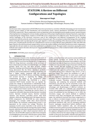
Rapidly acting static synchronous compensator STATCOM , a member of FACTS devices, is a capable technology being widely used as the state of the art dynamic shunt compensator for reactive power control in transmission and distribution system. In the last 25 years, technocrats have made extensive research on STATCOM technology due to which, many STATCOM controllers based on the self commutating solid state voltage source converter VSC have been developed and commercially put in operation to control system dynamics under stressed conditions. Because of its many attributes, STATCOM has emerged as a qualitatively superior controller relative to the line commutating static VAR compensator SVC . This controller is called with different terminologies as Static Compensator advanced static VAR compensator, advanced static VAR generator or static VAR generator, Static Condenser, synchronous solid state VAR compensator, VSC based SVC or self commutated SVC or static synchronous compensator SSC or S2C . The development of STATCOM controller employing various solid state converter topologies, magnetic configurations, control algorithms, switching techniques and so on, has been well reported in literature with its versatile applications in power system. A review on the state of the art STATCOM technology and further research potential are presented. Arjun Singh "A Review on Different Topologies and Control Method of Static Synchronous Compensator" Published in International Journal of Trend in Scientific Research and Development (ijtsrd), ISSN: 2456-6470, Volume-2 | Issue-6 , October 2018, URL: https://www.ijtsrd.com/papers/ijtsrd18729.pdf Paper URL: http://www.ijtsrd.com/engineering/electrical-engineering/18729/a-review-on-different-topologies-and-control-method-of-static-synchronous-compensator/arjun-singh<br>

E N D
International Journal of Trend in International Open Access Journal International Open Access Journal | www.ijtsrd.com International Journal of Trend in Scientific Research and Development (IJTSRD) Research and Development (IJTSRD) www.ijtsrd.com ISSN No: 2456 ISSN No: 2456 - 6470 | Volume - 2 | Issue – 6 | Sep 6 | Sep – Oct 2018 A Review on Different Topologies Static Synchronous Compensator Synchronous Compensator Different Topologies and Control Method Control Method of Arjun Singh M. Tech Scholar, Electrical Engineering Department YIET, Gadhauli YIET, Gadhauli, Yamunanagar, Haryana, India Tech Scholar, Electrical Engineering Department ABSTRACT Rapidly acting static synchronous compensator (STATCOM), a member of FACTS devices, is a capable technology being widely used as the state the-art dynamic shunt compensator for reactive power control in transmission and distribution system. In the last 25 years, technocrats have made extensive research on STATCOM technology due to which, many STATCOM controllers based on the self commutating solid-state voltage-source converter (VSC) have been developed and commercially put in operation to control system dynamics under stressed conditions. Because of STATCOM has emerged as a qualitatively superior controller relative to the line commutating static VAR compensator (SVC). This controller is called with different terminologies as Static advanced static VAR compensator, advanced static VAR generator or static VAR generator, Static Condenser, synchronous compensator, VSC-based SVC or self SVC or static synchronous compensator (SSC or S2C). The development of STATCOM controller employing various solid-state converter topologies, magnetic configurations, switching techniques and so on, has been well reported in literature with its versatile applications in power system. A review on the state STATCOM technology and further research potential are presented. Keywords:STATCOM; power structure; control structures I. INTRODUCTION The compensators based transformers of power named flexible alternating current (AC) transmission systems (FACTS) were current (AC) transmission systems (FACTS) were first introduced by N. G. Hingorani in 1988 [1]. Using electronic converters in the structures of these compensators provides several advantages such as high dynamic speed, low loss, and more accurate control. Therefore, running control functions in power systems while facing phenomena like the flicker, imbalance, harmonic pollution, behaviors will be more efficient and have a higher quality compared with the common compensators. One of FACTS devices, which has a positive and accurate function in regulating the voltage and compensating the flicker, is the synchronous static compensator (STATCOM). The STATCOM shunt-connected FACTS family member that can regulate the system bus voltage at transmission or distribution levels. Furthermore, it can inject harmonic currents to enhance the power quality of the power networks. Such controller gains in fact a voltage-source-based converter that can operate in both modes injecting or absorbing the reactive power. In comparison with other shunt devices like thyristor controlled reactor, thyristor switched reactor, thyristor switched capacitor, and thyristor controlle with fixed capacitor, which are identified as static Volt-Ampere Reactive (VAR) compensator, the STATCOM has some important advantages. For example, unlike other shunt family, the maximum compensating current is not dependent on the system bus voltage. Therefore, the maximum reactive power inject able to the system by the STATCOM is decreased with decreasing of the system voltage linearly, while this reduction is proportional to the square of voltage reduction in other shunt-connected devices [2]. Moreover, the STATCOM is superior to others from viewpoint of exchanging the active power with the power system when it is equipped with an energy source. In spite of when it is equipped with an energy source. In spite of Rapidly acting static synchronous compensator (STATCOM), a member of FACTS devices, is a capable technology being widely used as the state-of- art dynamic shunt compensator for reactive power control in transmission and distribution system. In the 25 years, technocrats have made extensive research on STATCOM technology due to which, many STATCOM controllers based on the self- first introduced by N. G. Hingorani in 1988 [1]. Using electronic converters in the structures of these provides several advantages such as high dynamic speed, low loss, and more accurate control. Therefore, running control functions in power systems while facing phenomena like the flicker, imbalance, harmonic pollution, efficient and have a higher quality compared with the common compensators. One of FACTS devices, which has a positive and accurate function in regulating the voltage and compensating the flicker, is the synchronous static compensator (STATCOM). The STATCOM is a connected FACTS family member that can regulate the system bus voltage at transmission or distribution levels. Furthermore, it can inject harmonic currents to enhance the power quality of the power networks. Such controller gains in fact a based converter that can operate in both modes injecting or absorbing the reactive power. In comparison with other shunt devices like thyristor controlled reactor, thyristor switched reactor, thyristor switched capacitor, and thyristor controlled reactor with fixed capacitor, which are identified as static Ampere Reactive (VAR) compensator, the STATCOM has some important advantages. For example, unlike other shunt-connected FACTS family, the maximum compensating current is not he system bus voltage. Therefore, the maximum reactive power inject able to the system by the STATCOM is decreased with decreasing of the system voltage linearly, while this reduction is proportional to the square of voltage reduction in ted devices [2]. Moreover, the STATCOM is superior to others from viewpoint of exchanging the active power with the power system and and transient transient source converter (VSC) have been developed and commercially put in dynamics under stressed conditions. STATCOM has emerged as a qualitatively superior controller relative to the line commutating static VAR compensator (SVC). This controller is called with Because of its its many many attributes, attributes, Compensator advanced static VAR compensator, advanced static VAR generator or static VAR generator, Static solid-state state VAR VAR based SVC or self-commutated SVC or static synchronous compensator (SSC or ent of STATCOM controller state converter topologies, magnetic configurations, switching techniques and so on, has been well reported in literature with its versatile applications in control control algorithms, algorithms, state-of-the-art STATCOM technology and further research potential STATCOM; power structure; control The transformers of power named flexible alternating compensators based on on the the electronic electronic @ IJTSRD | Available Online @ www.ijtsrd.com www.ijtsrd.com | Volume – 2 | Issue – 6 | Sep-Oct 2018 Oct 2018 Page: 738
International Journal of Trend in Scientific Research and Development (IJTSRD) ISSN: 2456 International Journal of Trend in Scientific Research and Development (IJTSRD) ISSN: 2456 International Journal of Trend in Scientific Research and Development (IJTSRD) ISSN: 2456-6470 power quality, several functions such as power system stability and power system operation are carried out by using the STATCOM. Correction of transient state stability is one of the most important objects. Equal area criterion shows that this compensator increases the margin of transient stability, that is, the “unused” and still available [2]. Power oscillation damping is another merit of STATCOM. Whendδ compensator has capacitive increases the transmitted power and is inductive when dδ/dt< 0 (δ is generator angle). This causes the oscillation in P and δ waveforms to be damped out. In recent years, useful and effective suggestions and ideas in the power and control structures of these compensators have been presented by creditable journals. Therefore, collecting, comparing, and analyzing the proposed methods and innovations can pave the way for researches. In fact, this paper establishes and provides a background where the advantages and disadvantages of different methods are revealed. After 2000, two creditable and comprehensive reviews were published in the field of STATCOMs. In the first review [3], published by Jose Rodriguez et al. in 2002, the structures, usages, and control methods in multilevel converters have been investigated and reviewed. In this paper, the multilevel structures have been categorized in a way as follows: (i) diode-clamped inverter; (ii) capacitor clamped inverter; (iii) cascaded multicell inverters; (iv) generalized multilevel cells; and (5) emerging multilevel inverter topologies (mixed multilevel cells, asymmetric hybrid multilevel cells, and soft-switched multilevel inverters) which was firstly introduced in [4]. The most important problem with diode-clamped inverters and the capacitor clamped inverters is that if, for example, there is n number of levels for the output voltage, by increasing the number of the levels, the number of diodes and capacitors is increased rapidly according to (n for the former inverter and to ((n-1) (n latter inverter. The increase in diode and cap count imposes limitations due to the complexity of the control algorithm and the bulkiness of the circuit. In spite of these drawbacks, one advantage is that they have common direct current (DC)-link voltage and do not suffer from voltage balancing addition, voltage levels have been increased without requiring accurate voltage matching. However, this can be a serious problem in high-voltage applications because using the common voltage source in this level not only is not practicable but also can reduce the reliability because all capacitors are dependent on one reliability because all capacitors are dependent on one power quality, several functions such as power system r system operation are carried out by using the STATCOM. Correction of transient state stability is one of the most important objects. Equal area criterion shows that this compensator increases the margin of transient stability, that is, the “unused” till available [2]. Power oscillation damping is another merit of STATCOM. Whendδ/dt> 0, the compensator has capacitive increases the transmitted power and is inductive when is generator angle). This causes the waveforms to be damped out. In recent years, useful and effective suggestions and ideas in the power and control structures of these compensators have been presented by creditable journals. Therefore, collecting, g the proposed methods and innovations can pave the way for researches. In fact, this paper establishes and provides a background where the advantages and disadvantages of different methods are revealed. After 2000, two creditable and were published in the field of STATCOMs. In the first review [3], published by Jose Rodriguez et al. in 2002, the structures, usages, and control methods in multilevel converters have been investigated and reviewed. In this paper, the s have been categorized in a way clamped inverter; (ii) capacitor- clamped inverter; (iii) cascaded multicell inverters; (iv) generalized multilevel cells; and (5) emerging multilevel inverter topologies (mixed-level hybrid cells, asymmetric hybrid multilevel cells, switched multilevel inverters) which was firstly introduced in [4]. The most important problem clamped inverters and the capacitor- clamped inverters is that if, for example, there is n f levels for the output voltage, by increasing the number of the levels, the number of diodes and capacitors is increased rapidly according to (n-1) (n-2) DC link. In the structures of cascaded multicell leg converters are put together in series in each phase, and the voltage of each phase is ding up the voltages of the converters of the same phase. This structure is much simpler than diode and capacitor-clamped inverter schemes. In generalized multilevel cells, the two- DC link. In the structures of cascaded multicell inverters, some two-leg converters are put together in series in each phase, and the voltage of each phase is obtained through adding up the voltages of the converters of the same phase. This structure is much simpler than diode and capacitor schemes. In generalized multilevel cells, the two level, three-level, and four-level to n put next to each other. In this design, every level of voltage is balanced by itself and independent from the characteristics of the load. In other words, this topology provides a multilevel structure that can balance any level of DC voltage by means of specialized controls. In mixed cells, the multilevel structures of diode inverter and capacitor-clamped inverter are replaced with the full-bridge cells in the cascaded multicell inverter schemes, and therefore, the number of DC sources is decreased. This method can be useful in high power and high-voltage applications. However, using diode-clamped and capacitor increases the complexity of the control algorithms. In asymmetric hybrid multilevel cells, the levels of the DC voltage in cells are not equal, and the converters of every cluster suffer from different stress. Although this can increase the cost, it causes more levels to be produced with the same number of devices when compared with symmetric multilevel inverters. Also, controlling the balance of the capacitor voltage in such scheme may be more difficult compared with the topologies where the voltages of all capacitors must be set in a fixed value. Therefore, the modulation circuit becomes more complex. Referring to the studies conducted in [5–10], the paper [3] has investigated the methods based on using soft switching and the combinations of the methods zero voltage transition and auxiliary resonant commutated pole. Also in [3], the modulation methods have been divided into two groups frequency and switching in the main frequency. The second review on STATCOM was published by B. Singh et al. in 2009 [11]. In this paper, they approached STATCOM with two perspectives of multilevel converters and multipul Referring to Reference [12], they have stated that the multilevel structures have preference over the multipulse ones, which is based on magnetic coupling. There are important reasons for this preference, for example, the implementation of a multipulse structure is costly and the multilevel converters, especially the cascade type, are more converters, especially the cascade type, are more level to n-level ones are er. In this design, every level of performance performance and and voltage is balanced by itself and independent from the characteristics of the load. In other words, this topology provides a multilevel structure that can balance any level of DC voltage by means of In mixed-level hybrid multilevel cells, the multilevel structures of diode-clamped clamped inverter are replaced bridge cells in the cascaded multicell inverter schemes, and therefore, the number of DC sed. This method can be useful in voltage applications. However, clamped and capacitor-clamped inverters increases the complexity of the control algorithms. In asymmetric hybrid multilevel cells, the levels of the in cells are not equal, and the converters of every cluster suffer from different stress. Although this can increase the cost, it causes more levels to be produced with the same number of devices when compared with symmetric multilevel inverters. Also, ntrolling the balance of the capacitor voltage in such scheme may be more difficult compared with the topologies where the voltages of all capacitors must be set in a fixed value. Therefore, the modulation circuit becomes more complex. Referring to the categorizing, categorizing, 10], the paper [3] has investigated the methods based on using soft switching and the combinations of the methods zero- voltage transition and auxiliary resonant commutated pole. Also in [3], the modulation methods have been of switching in high 1) (n-2))/2 for the frequency and switching in the main frequency. latter inverter. The increase in diode and capacitor count imposes limitations due to the complexity of the control algorithm and the bulkiness of the circuit. In spite of these drawbacks, one advantage is that they The second review on STATCOM was published by B. Singh et al. in 2009 [11]. In this paper, they approached STATCOM with two perspectives of multilevel converters and multipulse converters. Referring to Reference [12], they have stated that the multilevel structures have preference over the multipulse ones, which is based on magnetic coupling. There are important reasons for this preference, for example, the implementation of a multipulse structure is costly and the multilevel link voltage and do of levels. In addition, voltage levels have been increased without requiring accurate voltage matching. However, this voltage applications because using the common voltage source in this level t also can reduce the @ IJTSRD | Available Online @ www.ijtsrd.com www.ijtsrd.com | Volume – 2 | Issue – 6 | Sep-Oct 2018 Oct 2018 Page: 739
International Journal of Trend in Scientific Research and Development (IJTSRD) ISSN: 2456 International Journal of Trend in Scientific Research and Development (IJTSRD) ISSN: 2456 International Journal of Trend in Scientific Research and Development (IJTSRD) ISSN: 2456-6470 reliable. However, because each project has its own specific features, the role of the multipulse converters cannot be easily ignored. The control strategi reliable. However, because each project has its own specific features, the role of the multipulse converters cannot be easily ignored. The control strategies of STATCOM have been surveyed in [12], and the basis of the control architecture in STATCOM has been STATCOM have been surveyed in [12], and the basis of the control architecture in STATCOM has been reported as Figure 1 shows. Figure1. The basis of the control architecture in synchronous static compensator (STATCOM) [12] voltage-source converter; AC, alternating current; DC, direct current; GTO, gate turn converter; AC, alternating current; DC, direct current; GTO, gate turn converter; AC, alternating current; DC, direct current; GTO, gate turn-off thyristor. 1. The basis of the control architecture in synchronous static compensator (STATCOM) [12] 1. The basis of the control architecture in synchronous static compensator (STATCOM) [12] VSC, II. VSC is the backbone of STATCOM and it is a combination of self-commutating solid devices (viz. GTO, IGBT, IGCT and so on) wit reverse diode connected in parallel to them. The solid state switches are operated either in square mode with switching once per cycle or in PWM mode employing high switching frequencies in a cycle of operation or selective modulation employing low switching frequencies. A DC voltage source on the input side of VSC, which is generally achieved by a DC capacitor and output, is a multi-stepped AC voltage waveform, almost a sinusoidal waveform. The turn-off device makes the converter action, whereas diode handles rectifier action. STATCOM is essentially consisting of six pulse VSC units, DC side of which is connected to a DC capacitor to be used as an energy storage device, interfacing magnetics (main coupling transformer and/or inter-mediate/inter-phase transformers) that form the electrical coupling between converter AC output voltage (Vc) and system voltage (Vs) and a controller. The primary objective of STATCOM is to obtain almost harmonic neutralised and controllable harmonic neutralised and controllable three-phase AC output voltage waveforms at the point of common coupling (PCC) to regulate reactive current flow by generation and absorption of controllable reactive power by the solid switching algorithm. As STATCOM has inherent characteristics for real power exchange with a support of proper energy storage system, operation of such controller is possible in all four quadrants of Q plane [2] and it is governed by the following power flow relation: VV VV S j X X Where; S is the apparent power flow, P the active power flow, Q the reactive power flow, Vs the main AC phase voltage to neutral (rms), Vc the STATCOM fundamental output AC phase voltage (rms), L the leakage inductance, f the system frequency and a the phase angle between Vs a flow is influenced by the variation of a and reactive flow is influenced by the variation of a and reactive Working principle of STATCOM Working principle of STATCOM VSC is the backbone of STATCOM and it is a commutating solid-state turn-off devices (viz. GTO, IGBT, IGCT and so on) with a reverse diode connected in parallel to them. The solid- state switches are operated either in square-wave mode with switching once per cycle or in PWM mode employing high switching frequencies in a cycle of operation or selective dulation employing low switching frequencies. A DC voltage source on the input side of VSC, which is generally achieved by a DC capacitor and output, is a stepped AC voltage waveform, almost a hase AC output voltage waveforms at the point of common coupling (PCC) to regulate reactive current flow by generation and absorption of controllable reactive power by the solid-state switching algorithm. As STATCOM has inherent wer exchange with a support of proper energy storage system, operation of such controller is possible in all four quadrants of Q–P plane [2] and it is governed by the following power harmonic harmonic elimination elimination 2 VV X VV X V V X X (1) = = α α − − α α − − = = − − 3 sin 3 cos s s c c s s c c s s S j P P jQ jQ L L L L L L off device makes the ter action, whereas diode handles rectifier action. STATCOM is essentially consisting of six- pulse VSC units, DC side of which is connected to a DC capacitor to be used as an energy storage device, interfacing magnetics (main coupling transformer Vs the main AC phase voltage to neutral (rms), Vc the STATCOM fundamental output AC phase phase transformers) that form the electrical coupling between converter AC output voltage (Vc) and system voltage (Vs) and a controller. The primary objective of STATCOM is to L the leakage inductance, f the system frequency and a the phase angle between Vs and Vc. Active power @ IJTSRD | Available Online @ www.ijtsrd.com www.ijtsrd.com | Volume – 2 | Issue – 6 | Sep-Oct 2018 Oct 2018 Page: 740
International Journal of Trend in Scientific Research and Development (IJTSRD) ISSN: 2456 International Journal of Trend in Scientific Research and Development (IJTSRD) ISSN: 2456 International Journal of Trend in Scientific Research and Development (IJTSRD) ISSN: 2456-6470 power flow is greatly varied with the magnitude of the voltage variation between Vc and Vs. For lagging a, power (P) flows from Vc to Vs, for leading a, power (P) flows from Vs to Vc and for α=0, the P is zero and Q is derived from (1) as follows. V Q V V X The AC voltage output (Vc) of STATCOM is governed by DC capacitor voltage (Vdc) and it can be controlled by varying phase difference (a) between Vc and Vs (and also by m, modulation index for PWM control). The basic two level and three configurations and respective AC output voltage (Vc) waveforms corresponding to a square wave operation are illustrated in Figs. 1. Functionally, STATCOM injects an almost sinusoidal current (I) in quadrature (lagging or leading) with the line voltage (Vs), and emulates as an inductive or a capacitive reactance at the point of connection with the electrical system for reactive power control, and it is ideally the situation when amplitude of Vs is controlled from full leading (capacitive) to full lagging (inductive) for a equals to zero (i.e. both Vc and Vs are in the same phase). The magnitude and phase angle of the injected current (I) are determined by the magnitude and phase difference (a) between Vc and Vs across the leakage inductance (L), which in turn controls reactive power flow and DC voltage, Vdcacross the capacitor. STATCOM is considered to be operating in a capacitive mode. When Vc<Vs, it is operating in an inductive mode and for Vc =Vs, no reactive power exchange takes place. In the high rating STATCOM operated under fundamental frequency switching, the principle of phase angle control (α) is generally adopted in control algorithm to compensate converter losses by active power drawn from AC system and also for power flows in or out of the VSC to indirectly control the magnitude of DC voltage with charging or discharging of DC bus capacitor enabling control reactive power flow into the system. III. State-of-the-art solid-state switching devices and switching technology In power converter circuits various controllable solid state switches such as conventional thyristor, GTO, IGBT, IEGT, IGCT or GCT [164], bipolar junction transistor (BJT) and MOS field effect transistor are employed for various applications such as VSC, current-source converter and so on. Each device has source converter and so on. Each device has power flow is greatly varied with the magnitude of the voltage variation between Vc and Vs. For lagging a, power (P) flows from Vc to Vs, for leading a, power different operating characteristics in respect to switching frequency/speed, device ratings, turn-off on timings, forward and reverses breakdown state voltage drop, switching losses and so on. The conventional thyristor, a line commutating switching device available commercially at very high power ratings, is a mature technology and forms basic switching element for SVC, a second generation FACTS controller being used as a dynamic reactive power compensator. This power semiconductor off capability and relatively high response time. The emerging technology is solid-state off switches. These switches viz. GTO, IGBT, IGCT are being used extensively in converter circuits for controllers. Drive circuit requirements, switching different operating characteristics in respect to switching frequency/speed, device ratings, turn and turn-on timings, forward and reverses breakdown voltage, on-state voltage drop, switching losses and so on. The conventional thyristor, a line commutating switching device available commercially at very high power ratings, is a mature technology and for switching element for SVC, a second generation FACTS controller being used as a dynamic reactive power compensator. This power semiconductor device has no turn-off capability and relatively high response time. The emerging technology is solid controllable turn-off switches. These switches viz. GTO, IGBT, IGCT are being used extensively in converter circuits for controllers. Drive circuit requirements, switching frequency/speed. switching losses and cost of each device are the trade-off to use these devices effectively. Among the turn-off power switches, GTO thyristor is a mature technology and commercially available at high power ratings. Its extensive applications in high power rating converter cumcompensator circuits have ushered in a new era of FACTS controllers, for example, STATCOM, UPFC, convertible static compensator synchronous series compensator (SSSC) and so on. Solid-state IGBT switching device is a relatively new technology in power electronics i medium-to-high power ratings PWM controllers due to its high switching frequency and speed. Among the turn-off switches, IGCT is the most promising and emerging solid has the merits of low switching loss, high frequency/speed, no snubber circuit requirements. IGCT-converter-based high power rating STATCOM is under implementation stage at 138 kV Talegasub station in California. Because of relatively high cost, its commercial competitiveness is yet to explored. Switching topologies such as PWM or power frequency switching depend upon the type of solid-state devices used in STATCOM. Primarily, fundamental frequency method of switching (pulsed one per line frequency cycle) and PWM techniques (pulsed multi times per half cycle) are widely accepted methods. In PWM control, solid switches are operated many times at frequent intervals within the same cycle of output voltage, and an improved quality of output AC voltage waveforms [in terms of low amplitude of low total harmonic distortion (THD)] can be obtained. Based on the frequency and amplitude of triangular shape carrier signal and modulating control signal, shape carrier signal and modulating control signal, =0, the P is zero and (2) = − ( ) s c s L The AC voltage output (Vc) of STATCOM is governed by DC capacitor voltage (Vdc) and it can be controlled by varying phase difference (a) between Vc (and also by m, modulation index for PWM and three-level VSC configurations and respective AC output voltage (Vc) state state-of-the-art FACTS square wave mode of losses and cost of each off to use these devices off power switches, GTO jects an almost sinusoidal current (I) in quadrature (lagging or leading) with the line voltage (Vs), and emulates as an inductive or a capacitive reactance at the point of connection with the electrical system for reactive power control, and it the situation when amplitude of Vs is controlled from full leading (capacitive) to full lagging (inductive) for a equals to zero (i.e. both Vc and Vs are in the same phase). The magnitude and phase angle of the injected current (I) are determined agnitude and phase difference (a) between Vc and Vs across the leakage inductance (L), which in turn controls reactive power flow and DC voltage, Vdcacross the capacitor. STATCOM is considered to be operating in a thyristor is a mature technology and commercially available at high power ratings. Its extensive applications in high power rating converter- ave ushered in a new era of FACTS controllers, for example, STATCOM, UPFC, convertible static compensator synchronous series compensator (SSSC) and so on. state IGBT switching device is a relatively new technology in power electronics is employed in high power ratings PWM-based FACTS controllers due to its high switching frequency and off switches, IGCT is the most promising and emerging solid-state technology and has the merits of low switching loss, higher switching frequency/speed, no snubber circuit requirements. based high power rating STATCOM is under implementation stage at 138 kV Talegasub- station in California. Because of relatively high cost, its commercial competitiveness is yet to be fully explored. Switching topologies such as PWM or power frequency switching depend upon the type of state devices used in STATCOM. Primarily, fundamental frequency method of switching (pulsed one per line frequency cycle) and PWM techniques lsed multi times per half cycle) are widely accepted methods. In PWM control, solid-state switches are operated many times at frequent intervals within the same cycle of output voltage, and an improved quality of output AC voltage waveforms [in of low-order harmonics/low total harmonic distortion (THD)] can be obtained. Based on the frequency and amplitude of triangular (CSC), (CSC), static static When When Vc>Vs, Vc>Vs, the the s, it is operating in an inductive mode and for Vc =Vs, no reactive power exchange takes place. In the high rating STATCOM operated under fundamental frequency switching, the α) is generally compensate converter losses by active power drawn from AC system and also for power flows in or out of the VSC to indirectly control the magnitude of DC voltage with charging or discharging of DC bus capacitor enabling control of state switching devices In power converter circuits various controllable solid- state switches such as conventional thyristor, GTO, IGBT, IEGT, IGCT or GCT [164], bipolar junction transistor (BJT) and MOS field effect transistor are employed for various applications such as VSC, @ IJTSRD | Available Online @ www.ijtsrd.com www.ijtsrd.com | Volume – 2 | Issue – 6 | Sep-Oct 2018 Oct 2018 Page: 741
International Journal of Trend in Scientific Research and Development (IJTSRD) ISSN: 2456 International Journal of Trend in Scientific Research and Development (IJTSRD) ISSN: 2456 International Journal of Trend in Scientific Research and Development (IJTSRD) ISSN: 2456-6470 PWM converters are designed, in general, to eliminate triplen and other low order harmonics (5th/7th), and by means of suitable filter design, predominantly higher-order harmonics are reduced in the AC voltage output. As the converter conduction and switching losses are a function of switching frequency, the PWM technique is not generally adopted in high rating STATCOMs on account of high switching losses, whereas low-to medium rating STATCOMs used in power distribution system are built upon PWM control and such STATCOMs are generally termed D-STATCOM. IV. STATCOM topologies and configurations Many VSC-based topologies and configurations are adopted in the state-of-the-art STATCOM controllers and significantly, multi-pulse and/or multi topologies are widely accepted in the design of compensators. For example, a two-level multi topology is a mature topology and commercially adopted in +100 MVA STATCOM at 500/ 161 kV Sullivan S/S of Tennessee Valley Authority (TVA), US and in +80 MVA SVG at 154 kV Inuyama switching station of Kansai Electric Power Co. PWM converters are designed, in general, to eliminate ), Japan. An elementary six-pulse VSC which consists of three legs (phases) with two valves per leg and an electrostatic capacitor on the DC bus is illustrated in Fig. 2. Each valve consists of a self- commutating switch with a reverse diode connected in wave mode, eight possible switching states are possible with respect to the polarity of DC voltage source (Vdc). A set of three quasisquare waveforms at its AC terminals, displaced successively by 120 degree, is obtained using frequency switching modulation. The phase to neutral (0, +Vdc/3, +2Vdc/3) and line-to-line voltage (0, +Vdc) of the converter shown in Fig. 2 contain an unacceptable current harmonics causing severe harmonic interference to electrical system. To pulse converter topology derived from the combination of multiple number (N- (KEPC), Japan. An elementary six consists of three legs (phases) with two valves per leg and an electrostatic capacitor on the DC bus is illustrated in Fig. 2. Each valve consists of a self commutating switch with a reverse diode connected in parallel. In square-wave mode, eight possible switching states are possible with respect to the polarity of DC voltage source (Vdc). A set of three quasisquare waveforms at its AC terminals, displaced successively by 120 degree, is obtained using fundamental frequency switching modulation. The phase to neutral (0, +Vdc/3, +2Vdc/3) and line voltage (0, +Vdc) of the converter shown in Fig. 2 contain an unacceptable current harmonics causing severe harmonic interference to electrical system. To reduce THD, multi-pulse converter topology derived from the combination of multiple number (N numbers) of elementary six-pulse converter units to be triggered at specific displacement angle(s), is widely adopted, and output AC voltage waveforms from each unit is electro-magnetically added with an appropriate phase shift by inter to produce a multi-pulse (6 N pulses) waveform close to sinusoidal wave. harmonics (5th/7th), and by means of suitable filter design, predominantly order harmonics are reduced in the AC voltage output. As the converter conduction and switching losses are a function of switching frequency, the que is not generally adopted in high rating STATCOMs on account of high switching rating STATCOMs used in power distribution system are built upon PWM control and such STATCOMs are generally topologies and configurations based topologies and configurations are art STATCOM controllers pulse and/or multi-level topologies are widely accepted in the design of pulse converter units to level multi-pulse be triggered at specific displacement angle(s), is widely adopted, and output AC voltage waveforms magnetically added with an appropriate phase shift by inter-phase transformer(s) pulse (6 N pulses) waveform close topology is a mature topology and commercially adopted in +100 MVA STATCOM at 500/ 161 kV Sullivan S/S of Tennessee Valley Authority (TVA), US and in +80 MVA SVG at 154 kV Inuyama switching station of Kansai Electric Power Co. Figure 2 Basic two-level six-pulse VSC ulse VSC Bridge and its AC voltage output waveform in square operation Another variant of topology is a multi structure to generate multi-stepped voltage waveform close to sinusoidal nature. Owing to the complex series-parallel windings/circuits in multi-pulse converters, multi level configurations have been receiving increasing attention for high voltage and high power rating applications. In multi-level topology, a synthesised staircase voltage waveform is derived fr levels of DC voltage sources obtained normally by using capacitor voltage sources, and in this category, three-level converter topologies with square mode of operation is most common. mode of operation is most common. and its AC voltage output waveform in square-wave mode of In a multi-pulse converter configuration, the displacement angle between two consecutive six pulse converter is 2p/ (6N ) and three- contains odd harmonics component of the order of (6Nk + 1), where k ¼ 1, 2, 3, ... . With the increase in pulse number, lower-order harmonics are neutralised and a very close to sinusoidal AC output voltage waveform can be realised. Compared with basic six pulse converter, the multi-pulse configuration of STATCOM increases the achievable VAR rating, improves the harmonic performance, decreases the DC side current harmonics and reduces significantly the overall filter requirements. Basic two 6-pulse), 24 (4*6-pulse) and 6N (N 6 converter configurations are depicted in Figure 3. converter configurations are depicted in Figure 3. pulse converter configuration, the displacement angle between two consecutive six- Another variant of topology is a multi-level VSC stepped voltage waveform -phase voltage close to sinusoidal nature. Owing to the complex parallel mponent of the order of connection connection of of tr transformers (6Nk + 1), where k ¼ 1, 2, 3, ... . With the increase in order harmonics are neutralised and a very close to sinusoidal AC output voltage waveform can be realised. Compared with basic six- pulse converters, multi- level configurations have been receiving increasing attention for high voltage and high power rating level topology, a synthesised staircase voltage waveform is derived from several levels of DC voltage sources obtained normally by using capacitor voltage sources, and in this category, level converter topologies with square-wave pulse configuration of STATCOM increases the achievable VAR rating, improves the harmonic performance, decreases the DC side current harmonics and reduces significantly the overall filter requirements. Basic two-level 12 (2 6N (N 6-pulse)-pulse @ IJTSRD | Available Online @ www.ijtsrd.com www.ijtsrd.com | Volume – 2 | Issue – 6 | Sep-Oct 2018 Oct 2018 Page: 742
International Journal of Trend in Scientific Research and Development (IJTSRD) ISSN: 2456 Trend in Scientific Research and Development (IJTSRD) ISSN: 2456 Trend in Scientific Research and Development (IJTSRD) ISSN: 2456-6470 Figure 4 Multi-pulse parallel and series converter configurations pulse parallel and series converter configurations pulse parallel and series converter configurations V. The control system is the heart of state STATCOM controller for dynamic control of reactive power in electrical system. Based on the operational requirements, type of configuration and loss optimisation, essential control parameters are controlled performance and many control methodologies in STATCOM power circuits have been presented in [13]. In a square-wave mode of operation, phase angle control (a) across the leakage reactance (L) is the main controlling parameter. This control is employed in a two-level converter structure, where DC voltage (Vdc) is dynamically adjusted to above or equal t below the system voltage for reactive power control. In a three-level configuration, the dead- swell period (b) is controlled to vary the converter AC output voltage by maintaining Vdc constant. The control system for STATCOM operated wit mode employs control of α and m (modulation index) to change the converter AC voltages keeping Vdc constant. VI. Conclusions STATCOM is the state-of-the-art dynamic shunt compensator in FACTS family, which is widely used to control system dynamics under stressed condition. The self-commutating VSC built upon controllable solid-state devices (viz. GTO, IGBT, IGCT and so on) with operation under FFS or PWM switching principle is the backbone of this compensator. Many commendable features of STATCOM viz. four quadrant operation in P–Q plane (in support of proper energy source), high speed of response (sub versatile controlling and operational characteristics, optimum voltage platform and so on, have been reported in research publications. STATCOM being a versatile reactive power compensator has taken the place of the line commutating SVC, a relatively slow acting dynamic shunt controller. The EPRI in USA, who is a pioneer to conduct research and evolve high power rating STATCOMs employing GTO its backbone, has developed a number of existing has developed a number of existing STATCOM projects in collaboration with many utilities/ organisations. References 1.Padiyar K R. FACTS Controllers in Power Transmission and Tunbridge Wells; 2009. 2.Hingorani N G, Gyugyi L. Understanding FACTS: Concepts and Technology of Flexible AC Transmission Systems. Institute of Electrical and Electronics Engineers: New York; 1999. 3.Rodriguez J, Lai J-S, Peng F inverters: a survey of topologies, controls, and applications. IEEE Transactions on Industrial Electronics 2002; 49(4):724 4.Song B M, Gurol S, Jeong C S. A soft-switching high filter with flying capacitors for urban maglev system applications, in Conf. Rec. IEEE Annu. Meeting, Chicago, IL, 2001; 1461 5.Song B M, Lai J S. A multilevel soft inverter with inductor Transactions on Industry Applications 2001; 37:628–636. 6.Yuan X, Orgimeister G. ARCPI resonant snubber for the neutral point-clamped (NPC) inverter. IEEE Transactions on Industry Applications 2000; 36:586–595. 7.Yuan X, Barbi I. Zero voltage switching for level capacitor clamping Transactions on Power Electronics 1999; 14:771 781. 8.Yuan X. A transformer assisted zero switching scheme for the neutral (NPC) inverter, in Proc. IEEE APEC’99, 1999; 1259–1265. 9.Dijkhuizen F R, Duarte J L, van Gorningen WDH. Multilevel converter with auxiliary resonant Multilevel converter with auxiliary resonant Control strategies The control system is the heart of state-of-the-art STATCOM controller for dynamic control of reactive STATCOM projects in collaboration with many the operational requirements, configuration and loss optimisation, essential control parameters are controlled type of applications, applications, system system R. FACTS Controllers in Power Transmission and to to obtain obtain methodologies in desired desired Distribution. Distribution. Anshan: Anshan: STATCOM power circuits have been presented in wave mode of operation, phase angle control (a) across the leakage reactance (L) is the main controlling parameter. This control is employed level converter structure, where DC voltage (Vdc) is dynamically adjusted to above or equal to or below the system voltage for reactive power control. G, Gyugyi L. Understanding FACTS: Concepts and Technology of Flexible AC Transmission Systems. Institute of Electrical and nics Engineers: New York; 1999. S, Peng F Z. Multilevel inverters: a survey of topologies, controls, and applications. IEEE Transactions on Industrial Electronics 2002; 49(4):724–738. -angle or zero- swell period (b) is controlled to vary the converter AC output voltage by maintaining Vdc constant. The control system for STATCOM operated with PWM and m (modulation index) to change the converter AC voltages keeping Vdc M, Gurol S, Jeong C Y, Yoo D W, Lai J switching high-voltage active power filter with flying capacitors for urban maglev system applications, in Conf. Rec. IEEE-IAS Annu. Meeting, Chicago, IL, 2001; 1461–1469. S. A multilevel soft-switching inductor inverter Transactions on Industry Applications 2001; with coupling. coupling. IE IEEE art dynamic shunt compensator in FACTS family, which is widely used to control system dynamics under stressed condition. commutating VSC built upon controllable state devices (viz. GTO, IGBT, IGCT and so on) operation under FFS or PWM switching principle is the backbone of this compensator. Many commendable features of STATCOM viz. four Q plane (in support of proper energy source), high speed of response (sub-cycle), g and operational characteristics, optimum voltage platform and so on, have been reported in research publications. STATCOM being a versatile reactive power compensator has taken the place of the line commutating SVC, a relatively slow- controller. The EPRI in USA, who is a pioneer to conduct research and evolve high power rating STATCOMs employing GTO-VSCs as Yuan X, Orgimeister G. ARCPI resonant snubber clamped (NPC) inverter. IEEE Transactions on Industry Applications 2000; Yuan X, Barbi I. Zero voltage switching for three level capacitor clamping Transactions on Power Electronics 1999; 14:771– inverter. inverter. IEEE IEEE Yuan X. A transformer assisted zero-voltage switching scheme for the neutral-point-clamped (NPC) inverter, in Proc. IEEE APEC’99, 1999; L, van Gorningen WDH. @ IJTSRD | Available Online @ www.ijtsrd.com www.ijtsrd.com | Volume – 2 | Issue – 6 | Sep-Oct 2018 Oct 2018 Page: 743
International Journal of Trend in Scientific Research and Development (IJTSRD) ISSN: 2456 International Journal of Trend in Scientific Research and Development (IJTSRD) ISSN: 2456 International Journal of Trend in Scientific Research and Development (IJTSRD) ISSN: 2456-6470 15.Jiang Y, Ekstrom A. Applying PWM to control overcurrents at unbalanced faults of forced commutated VSCs compensators. IEEE Transactions on Power Delivery 1997; 12(1):273– 16.Tang Y, Xu L. A new converter topology for advanced static VAR compensation in high power applications. IEEE Industry Applications Society Annual Meeting, Conf. Record, 2 1993, vol. 2, pp. 947–953 17.Wuest D. An improved PWM optimization method for a static reactive power compensator with self-commutated inverter. PESC Power Electr. Specialists Conf., Camb 521–529. 18.Malesani L, Tomasin P. PWM current control techniques of voltage source converters survey, Int. Conf. Proc. Industrial Electronics, Control and Instrumentation, IECON’93, 15 November 1993, vol. 2, pp. 670 November 1993, vol. 2, pp. 670–675. commutated pole, in Conf. RecIEEE Meeting, 1998; 1440–1446. 10.Teichmann R, O’Brian K, Bernet S. Comparison of multilevel ARCP topologies, in Proc. Int. Power Electronics Conf., Tokyo, Japan, 2000; 2035–2040. 11.Singh B, Saha R, Chandra A, Al-Haddad K. Static synchronous compensators review. IET Power Electronics 2009; 2(4):297 324. 12.Lai J-S, Peng F Z. Multilevel converters breed of power converters. IEEE Transactions on Industry Applications 1996; 32(3):509 13.Tahri A, Draou A, Benghanem M. A fast current control strategy of a PWM inverter used for static VAR compensation. Proc. IEEE 24th Annual Conf. Industrial Electronics Society, IECON’98, 31 August– 4 September 1998, vol. 1, pp. 450 455 14.Wuest D, Jenni F. Space vector based current control schemes for voltage source inverters. IEEE Power Electronics Specialists Conf., PESC’93, 20–24 June 1993; 986–992. commutated pole, in Conf. RecIEEE-IAS Annu. Jiang Y, Ekstrom A. Applying PWM to control currents at unbalanced faults of forced- commutated VSCs compensators. IEEE Transactions on Power –278. used used as as static static VAR VAR Teichmann R, O’Brian K, Bernet S. Comparison of multilevel ARCP topologies, in Proc. Int. cs Conf., Tokyo, Japan, 2000; Tang Y, Xu L. A new converter topology for advanced static VAR compensation in high power Industry Applications Society Annual Meeting, Conf. Record, 2–8 October Haddad K. Static synchronous review. IET Power Electronics 2009; 2(4):297– compensators (STATCOM): (STATCOM): a a Wuest D. An improved PWM optimization method for a static reactive power compensator commutated inverter. PESC Power Electr. Specialists Conf., Cambridge, MA, 1991; Z. Multilevel converters – a new E Transactions on Industry Applications 1996; 32(3):509–517. Tahri A, Draou A, Benghanem M. A fast current control strategy of a PWM inverter used for static VAR compensation. Proc. IEEE 24th Annual Conf. Industrial Electronics Society, IECON’98, 4 September 1998, vol. 1, pp. 450– Malesani L, Tomasin P. PWM current control techniques of voltage source converters – a survey, Int. Conf. Proc. Industrial Electronics, Control and Instrumentation, IECON’93, 15–19 Wuest D, Jenni F. Space vector based current control schemes for voltage source inverters. IEEE Power Electronics Specialists Conf., 992. @ IJTSRD | Available Online @ www.ijtsrd.com www.ijtsrd.com | Volume – 2 | Issue – 6 | Sep-Oct 2018 Oct 2018 Page: 744