Download
1 / 6
60 likes | 92 Vues
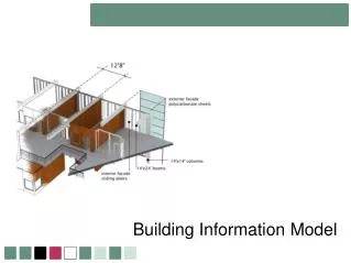
From the past few decades, Building Information Modeling BIM has been evolving to become one of the robust domains connecting different dimensions from Architecture, Engineering and Constructions. Even though it was started to take over a large part of the globe in understanding various components of structure, it is yet to reach a common person for generating a 3D building for an given area. In this study, a three dimensional graphical user interface is developed to generate a 3D building from given parameters such as height of the each floor, number of bays in each direction, dimensions of major structural elements and information related to windows and doors. The future work of this tool is to give different three dimensional structures for any given plan including its analysis, design and material quantities at any location of the globe considering local structural types with inclusion of structural standard codes. Trishala Daka | Vineesha Doppalapudi | Gamanash Kommineni | Prannoy Anand Noel | Venkata Dilip Kumar Pasupuleti "Building Information Model: A Graphical User Interface to Generate a three Dimensional Building" Published in International Journal of Trend in Scientific Research and Development (ijtsrd), ISSN: 2456-6470, Special Issue | International Conference on Advanced Engineering and Information Technology , November 2018, URL: https://www.ijtsrd.com/papers/ijtsrd19125.pdf Paper URL: https://www.ijtsrd.com/engineering/civil-engineering/19125/building-information-model-a-graphical-user-interface-to-generate-a-three-dimensional-building/trishala-daka<br>

E N D
International Journal of Trend in Scientific Research and International Conference on Advanced Engineering and Information Technology (ICAEIT-2017) Building Information Model: A Graphical User Interface Generate a three Dimensional Building International Journal of Trend in Scientific Research and Development (IJTSRD) International Conference on Advanced Engineering and Information Technology ISSN No: 2456 - 6470 | www.ijtsrd.com | Special Issue International Conference on Advanced Engineering ISSN No: 2456 Special Issue Publication Building Information Model: A Graphical User Interface Generate Trishala Daka1, Vineesha Doppalapudi Venkata Dilip Kumar Pasupuleti 1Undergraduate Student, School of Engineering Sciences, Mahindra Ecole Centrale, College of Engineering, Hyderabad, School of Engineering Sciences, Mahindra Ecole Centrale, College of Engineering, Hyderabad, Telangana, India Building Information Model: A Graphical User Interface to , Vineesha Doppalapudi1, Gamanash Kommineni1, Prannoy Anand Venkata Dilip Kumar Pasupuleti2 Undergraduate Student, 2Assistant Professor School of Engineering Sciences, Mahindra Ecole Centrale, College of Engineering, Hyderabad, Prannoy Anand Noel1, ABSTRACT From the past few decades, Building Information Modeling (BIM) has been evolving to become one of the robust domains connecting different dimensions from Architecture, Engineering and Constructions. Even though it was started to take over a large part of the globe in understanding various components of structure, it is yet to reach a common person for generating a 3D building for an given area. In this study, a three dimensional graphical user interface is developed to generate a 3D building from given parameters such as height of the each floor, number of bays in each direction, dimensions of major structural elements and information related to windows and doors. The future work of this tool is to give different three dimensional structures for any given plan including its analysis, design and material quantities at any location of the globe considering local structural types with inclusion of structural standard codes. Keywords: Building Information Model plans, 3D building modeling, MATLAB, User Interface (GUI), product development 1.Introduction Earlier contractors and designers used to face a lot of complications during the construction or after the completion of the project like failure or tilting of the structure even though they were designed very well and perfectly executed according to the p occur due to the misinterpretations during the design period of the structure. So, from the past few years to period of the structure. So, from the past few years to overcome such incidents many companies in Architecture, Engineering, and have realized major IT-based change p their operations [1]. These technologies, commonly referred to as Building Information are emerging with IT- based information systems which promote collaborative and integrated design, assembly, and operation of buildings. BIM termed as a platform of IT tools engaged to design virtual models working to present all physical and functional characteristics of a building [2].After the development of BIM which has complete the building, researchers have starte on detailing or information towards a structure or building. For example, regular computer software imitates traditional hand drafting, in which drawings are almost in 2D, with lines and arcs signifies objects in floor plans, plans and details [3]. In late different kind of design software was developed. Instead of imitating hand drafting, it uses 3D models to represent the real world structures that make up buildings, such as the walls, doors. In fact, a true BIM model consists of the virtual and essential equivalents of segments that are used to complete a building. The digital 3D model not only contains architectural data but also has information regarding physical and functional characteristics of the traditional building elements such as walls, columns, doors, staircase etc. If there are any modifications in any of these structural elements, each section view, elevation, floor structural elements, each section view, elevation, floor From the past few decades, Building Information Modeling (BIM) has been evolving to become one of the robust domains connecting different dimensions from Architecture, Engineering and Constructions. started to take over a large part of the globe in understanding various components of structure, it is yet to reach a common person for generating a 3D building for an given area. In this study, a three dimensional graphical user interface is generate a 3D building from given parameters such as height of the each floor, number of bays in each direction, dimensions of major structural elements and information related to windows and doors. The future work of this tool is to give different dimensional structures for any given plan including its analysis, design and material quantities at any location of the globe considering local structural types with inclusion of structural standard overcome such incidents many companies in Architecture, Engineering, and Construction industry based change processes in their operations [1]. These technologies, commonly referred to as Building Information Modelling (BIM), based information systems which promote collaborative and integrated design, assembly, and operation of buildings. BIM can be best termed as a platform of IT tools engaged to design virtual models working to present all physical and functional characteristics of a building [2].After the development of BIM which has complete details of have started to focus more information towards a structure or building. For example, regular computer aided design traditional hand drafting, in which drawings are almost in 2D, with lines and arcs signifies objects in floor plans, elevations, framing late 1980‟s, a completely different kind of design software was developed. Instead of imitating hand drafting, it uses 3D models to represent the real world structures that make up buildings, such as the walls, floors, windows and doors. In fact, a true BIM model consists of the virtual Model (BIM), 2D MATLAB, Graphical Interface (GUI), product development of the actual building Earlier contractors and designers used to face a lot of complications during the construction or after the completion of the project like failure or tilting of the structure even though they were designed very well and perfectly executed according to the plan. These occur due to the misinterpretations during the design segments that are used to complete a building. The digital 3D model not only contains architectural data regarding physical and functional characteristics of the traditional building elements such as walls, columns, doors, staircase etc. If there are any modifications in any of these @ IJTSRD | Available Online @ www.ijtsrd.com | Special Issue Publication | November 2018 @ IJTSRD | Available Online @ www.ijtsrd.com | Special Issue Publication | November 2018 @ IJTSRD | Available Online @ www.ijtsrd.com | Special Issue Publication | November 2018 P - 145
International Journal of Trend in Scientific Research and Development (IJTSRD) | ISSN: 2456-647 plan will be automatically updated with the new change in the model. This allows the engineers to understand and simulate the structures even before the construction initiates. Junang and team had developed software to reconstruct 3D buildings from 2D vector floor plan [4-5]. But till now there has not been enough research on building a BIM tool for a common person who can see complete three dimensional building from a simple input of area and location of the built area. This research mainly focuses to develop a graphical user interface where a common person can enter the details of the plot area and its location irrespective of the geographical boundaries, and the developed tool will be able to suggest a user with wide varieties of the building types based on the location. And when the building type is selected the user would be able to see the complete three dimensional building, with the analysis and design results. This should be able to give quantity estimation with approximation pricing of the selected structure. In this paper a very fundamental graphical user interface developed is presented which can develop a complete three dimensional building with certain input parameters from the user. The study will be carried out further in the future to build a complete tool which can be used by any common person for building their dream houses. 2.Background Currently in most of the developed tools architectural drawings are either scanned or imported to develop a three dimensional plan. Dosch presented a system for the analysis of architectural drawings by dividing the whole area into tiles, and each of them being processed and analyzed independently [5]. Ahmed and their team converted the raster image into vector image except [6] which proposed directly on the raster image. Or proposed a highly automated approach to generate 3D plans from a 2D floor plan assuming poly lines to a wall [7]. Kishen devised a 3-Phase recognition approach to generate a 3D building from a 2D floor plan assuming closed boxes as walls [8]. Park suggested a method for recognizing main walls based on extension line [9]. Zhu had provided a detailed review on techniques which were used to convert 2D floor plans into 3D buildings. In their paper, they have discussed a new reconstruction method for 3D building from 2D vector plans [10]. From 2D drawings it is difficult to visualize the space management and BIM helps to eliminate the inappropriate designs. According to a report from McGraw Hill Construction regarding the extension of BIM in the infrastructure in the recent years, about 31% are using BIM on 75% or more of their projects in the year 2013 and in the 2009 it was 7%.The percentage that is not using BIM on 25% or less of their projects was rapidly decreased from 73% in 2009 to 21% in 2013 [11]. Implementing the Building Information Model does not simply create the production of construction but also operates as a support to the results from design and structural analysis to contribute to keep the data at one location. With the current technology it would be possible to add an additional segment to BIM where an user can just enter the area and location to get complete details of his or her structure. And this study focuses towards that. 3.Components of BIM There are majorly four components of BIM, Planning, Designing, Analysis, and Implementation. Even though the current section is in generic with BIM tool but it is background for development of this tool. And the details of four components have been detailed. 3.1. Planning The developed tool should be able to plan the structure depending on the availability of local materials and geographical location. 3.1.1. Quantify: To express the cost of members or elements used BIM collects and counts the amount of members. 3.1.2. Qualify: The status of any member can be identified by using BIM. This means that it provides information about the behaviour of the member and if it is fabricated. 3.2. Design The design is governed by the vision of the user and it is a process which may change due to constraints. 3.2.1. Specify: The designer has to identify the needs and select members according to the requirement. Similarly BIM generator determines if there is a need for a specific element. 3.2.2. Arrange BIM places the selected element in a pre-determined location. So BIM produces results according to the user’s requirement. @ IJTSRD | Available Online @ www.ijtsrd.com | Special Issue Publication | November 2018 P - 146
International Journal of Trend in Scientific Research and Development (IJTSRD) | ISSN: 2456-647 3.2.3. Scale BIM determines the size and magnitude of the element which is specified. 3.3. Analysis The viability of a member is determined by analysis. BIM examines and evaluates the results obtained. There are different types of analysis like energy analysis, Structural analysis, Lighting analysis, Mechanical analysis. 3.2.1. Coordinate: The members designed have to be effective and should work in conjunction with one another. This relationship is ensured by BIM. This helps achieve the design purpose of various elements during design, co- ordination, fabrication and installation. 3.2.2. Simulate: BIM predicts the future performance of members and elements used. This helps the user in understanding how the structure works in long run. 3.2.3. Check: BIM validates information of members. This also includes checking information for accuracy and assures that it is rational and reasonable. 3.3. Implementation The information obtained from BIM is used to construct members accordingly. It is this ability that eventually leads to the increased efficiency of construction. 3.3.1. Fabricate: Using the information obtained, the user has to manufacture members. BIM can generate models to fabricate replacement parts that can be used in future. 3.3.2. Assemble: The different members manufactured are to be brought together and assembled. The inaccuracies thus occurring will be minimal as it eliminates manual errors. 4.Flowchart Figure-1 explains the flow chart of the methodology carried for this study. Figure1. Work flow of the Project Requirements and inputs are taken from the user and are given a shape through 2D drawings. Secondly these drawings are developed to 3D digital models using image processing. The user is given a choice @ IJTSRD | Available Online @ www.ijtsrd.com | Special Issue Publication | November 2018 P - 147
International Journal of Trend in Scientific Research and Development (IJTSRD) | ISSN: 2456-647 depending on the feasibility of construction of the structure in that particular area. The challenges in each case are discussed to identify why it is worth analyzing. The disadvantages of each scenario have to be identified and addressed along with the main problem. This process will reveal the innovation of the project. The third part of the study will adopt a strategy to overcome these challenges. Conclusions are made and final detailed drawings are submitted to the end user. With the known land area and user requirements, 2D drawings are obtained and 3D digital model is generated with variations in the structural elements (like roof with slope or flat, height of individual areas etc.). This is followed by analysis using stiffness matrix method and design details. To make the study simple and understanding, the flow chart is divided into three parts. 4.1. User As per the prerequisites of the user such as location, type of house and aesthetic appeal, a different 2D plan is provided in order to congregate these requirements. Depending on plot area and constraints most appropriate plan is selected. 4.2. Generation of Three Dimensional Building From the scanned image of the plan using image processing technique, basic 3D structure is developed. Based on the preferences of the user, the roof of the building is selected and all the structural elements are added to the building. At this stage, final 3D structure is obtained with all the specifications. 4.3. Analysis, Design and Estimation This 3D model is further analyzed where the structure is subjected to different loads such as earthquake, wind and snow and their combinations depending upon the geographical conditions. Modifications are made to the final structure as per the analysis report. Design details of the structure are provided followed by quantity estimation of the building to know the capital required for total construction. Final designs and estimations are put forth to the user. 5.Modeling This paper presents preliminary results obtained from a developed code for a single bay structure with the inputs such as height of the structure, column and beam dimensions etc. For this purpose, MATLAB GUI platform was utilized for its ease. Generally structures are modeled with three basic geometries point, lines and areas. By connecting these areas, a closed structure in 3D is formed. For any point, 3 coordinates are defined in three dimensional space. Assuming the first point to be a(x, y, z) and connecting this point with another point b(x1, y1, z1), a line is formed. Connecting four such lines, a surface (rectangular) is generated and grouping these surfaces gives a 3D model. Structural bay is the span from one vertical element to the immediate adjacent vertical element. A bay consists of four columns, four beams, slab, walls, door and window. 5.1. Columns With reference to figure 2, first column is at the origin. The coordinates of the second column are obtained by shifting the coordinates of the first column in y direction. Similarly, the third and fourth columns are obtained by shifting the first column in x and y direction and y direction respectively. Figure2. Generation of column elements 5.2. Beams Beams are situated on the tops of the columns. Each beam is supported at either ends by two columns. With the co-ordinates of the top surface of the columns known, by connecting the required points, the bottom surface of the beam is formed. These coordinates are then shifted in the z direction to obtain the beam. Similarly, the remaining three beams are obtained as seen in fig-3. 5.3. Slabs Slab is located on the top of four beams. By connecting the corners of the four beams, the outline of the bottom surface of the slab is obtained. The slab is completed by shifting the coordinates in z direction and generated slab is shown in the fig-4. @ IJTSRD | Available Online @ www.ijtsrd.com | Special Issue Publication | November 2018 P - 148
International Journal of Trend in Scientific Research and Development (IJTSRD) | ISSN: 2456-647 respective directions to form the doors or windows based on the requirement from the user. And single bay developed three dimensional model can be seen in fig-6. 5.4. Walls Walls are situated in between the columns. To get the wall, the points are connected such that the surfaces formed will cover the empty space between the columns as shown in the fig-5. Figure3. Generation of beams over columns Figure6. Door and Windows with walls, slab, beams and columns Figure7. Developed GUI tool Figure4. Slab with beams and columns 6.Conclusions and future Work Conclusions of the current study are, with the current available computer programs and hard work, it is not a very difficult challenge to develop a tool which can generate the complete three dimensional structures with all the details. And the future work of this study will be (i) taking input as area from the user and providing the user with different plans or directly taking the scanned image of the plan if the user already has one, (ii) generating the three dimensional building which has already been developed and showcased in this paper, (iii) doing complete analysis and design based on geographical location, (iv) developed tool will be able to generate 2D and 3D diagrams of complete designs which can be understood by any common person or user. All the above work has its own challenges, which will be discussed in the extension of this paper. Figure5. Walls with slab, beams and columns 5.5. Doors and Windows Door and windows will be on the walls or practically in between the wall, so the co-ordinates of the four points forming the wall should be identified to form a small surface. These co-ordinates are then reduced in @ IJTSRD | Available Online @ www.ijtsrd.com | Special Issue Publication | November 2018 P - 149
International Journal of Trend in Scientific Research and Development (IJTSRD) | ISSN: 2456-647 Floor Document Analysis and Recognition (ICDAR), 2011, 864–869. Plans", International Conference on 7.References 7.1Journal Articles 1.U Gal, T Jensen, “Organizational Identity and the Appropriation of Information Systems”, ICIS 2008 Proceedings, pp.305-308., 2008 7.S. Or, K. H. Wong, Y. Yu, M. M. Chang, and H. Kong, "Highly automatic approach to architectural floor plan image understanding and model generation", Proc. Vision, Visualization, IOS Press, 2005, 723-734. 2.National Washington DC, “United States National Building Information Modelling Standard―Final Report, December 2007”. Institute of Building Sciences, Modelling, and 8.R. K Moloo, M. J Sheik Dawood, A. Salmaan Auleear, "3-Phase Recognition Approach to Pseudo 3D Building Generation from 2D Floor Plan", International Journal of Computer Graphics & Animation, 1(2), 2011, 13-27. 3.G Ralph, “CAD and BIM: Is there a Free Pass” A Report on Graph soft ArchiCAD‟s DWG workflow. 2010 4.J.Zhu, H. Zhang and Y. Wen, “A New Reconstruction Method for 3D Buildings from 2D Vector Floor Plan”, Computer-Aided Design and Applications, Volume No.11, Issue No.6, PP 704- 714. 2014. 9.J. Park, Kwon, Y.B: “Main wall recognition of architectural drawings using dimension extension line, Graphics Recognition”, Recent Advances and Perspectives, LNCS 3088, 2004, 116–127. 5.P. Dosch, G. Masini, "Reconstruction of the 3D Structure of a Building from the 2D Drawings of its Floors", Proceedings of the Fifth International Conference on Document Recognition, 2005, 487–490. 10.Junfang Zhu, Hui Zhang, Yamei Wen. “A new reconstruction method for 3D buildings from 2D vector floor plan. Computer-Aided Design and Applications”, Jun 2013, Lombardy, Italy. 2013. Analysis and 11.Hunt, Cesar Augusto, "The Benefits of Using Building Information Modelling in Structural Engineering"2013. 6.S. Ahmed, M. Liwicki, M. Weber and A. Dengel, "Improved Automatic Analysis of Architectural @ IJTSRD | Available Online @ www.ijtsrd.com | Special Issue Publication | November 2018 P - 150