Download
1 / 4
40 likes | 60 Vues
Three phase induction motors are the most common and frequently encountered machines in industry. This type of machines has simple in design and easy to maintain. This project deals with study and analysis of performance of induction motor and study and implementation of various possible controllers using vector control scheme. The PI and PID controller has been discussed and literature survey has been carried out. On the basis of literature survey PI and PID control system are developed here. Mr. Swapnil S. Managule | Dr. E Vijay Kumar "The Shunt Active Power Filter to Compensate Reactive Power and optimized THD with Improved Power by PI controller in a 3 Phase 3 Wire Distribution Network" Published in International Journal of Trend in Scientific Research and Development (ijtsrd), ISSN: 2456-6470, Volume-2 | Issue-5 , August 2018, URL: https://www.ijtsrd.com/papers/ijtsrd18197.pdf Paper URL: http://www.ijtsrd.com/engineering/electrical-engineering/18197/the-shunt-active-power-filter-to-compensate-reactive-power-and-optimized-thd-with-improved-power-by-pi-controller-in-a-3-phase-3-wire-distribution-network/mr-swapnil-s-managule<br>

E N D
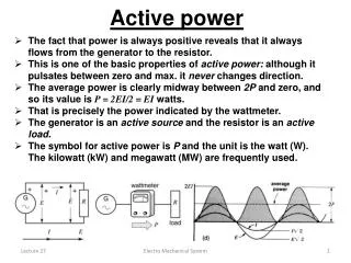
International Research Research and Development (IJTSRD) International Open Access Journal Compensate Reactive Power and International Journal of Trend in Scientific Scientific (IJTSRD) International Open Access Journal ISSN No: 2456 ISSN No: 2456 - 6470 | www.ijtsrd.com | Volume 6470 | www.ijtsrd.com | Volume - 2 | Issue – 5 The Shunt Active Power Filter to Optimized THD with Improved Power by PI C Wire Distribution Network Wire Distribution Network The Shunt Active Power Filter to Compensate Reactive Power and THD with Improved Power by PI Controller in a 3 Phase 3 ontroller in a 3 Phase 3 Mr. Swapnil S. Managule1, Dr. E Vijay Kumar2 cholar, 2Head of Electrical & Electronics Engineering , Sarvepalli Radhakrishnan University, Mr. Swapnil S. Managule 1M.Tech. Scholar, RKDF Institute of Science & Technology Institute of Science & Technology, Sarvepalli Radhakrishnan Uni Bhopal, Madhya Pradesh, India ngineering ABSTRACT Three phase induction motors are the most and frequently encountered machines in industry. This type of machines has simple in design and easy to maintain. This project deals with study and analysis of performance of induction motor and study and implementation of various possible controlle vector control scheme. The PI and PID controller has been discussed and literature survey has been carried out. On the basis of literature survey PI and PID control system are developed here. Keywords: Active Power Filter, threshold harmonics distortions, quality factor, transfer function, hysteresis etc. I. INTRODUCTION The use of induction motors has increased tremendously since the day of its invention. They are being used as actuators in various industrial processes, robotics, house appliances (generally single phase) and other similar applications. The reason for its day by day increasing popularity can be primarily attributed to its robust construction, simplicity in design and cost effectiveness. These have also proved to be more reliable than DC motors. Apart from these advantages, they have some unfavorable features like their time varying and non-linear dynamics. Three phase induction motors are the most common and frequently encountered machines in industry, because this type of machines has a simple design and easy II. INDUCTION MOTOR SPEED CONTROL An easy way to comply with the conference for speed control of induction motor different controllers such control of induction motor different controllers such as conventional PI and PID controllers are used. When the load is applied on the mot speed decreases. This decreased speed will be feedback to the summation block .The summation block consist of two inputs, that is the feedback speed and the reference speed. The error signal is developed from both this inputs which is fed to t controller where all these controllers acts and brings back the speed to the reference value. From here throughout the process the speed remains constant for a constant load applied on it. So the advantage of using different controller is that e on a motor the reference speed can be obtained which cannot be obtained in open loop system. Therefore the closed loop system using PI, PID controller has been achieved in this paper. After getting the speed response for different controllers, the results are compared. Speed control techniques for induction motor drive which we are using in this Paper is 1.Speed response of induction motor in open loop System. 2.Speed control of induction motor in closed loop system using PI Controller. 3.Speed control of induction motor in closed loop system using PID Controller. III. POWER QUALITY The PQ issue is defined as “any occurrence manifested in voltage, current, or frequency deviations that results in damage, upset, failure, or mis-operation of end-use equipment.” Almost all PQ issues are closely related with PE in almost every issues are closely related with PE in almost every Three phase induction motors are the most common and frequently encountered machines in industry. This type of machines has simple in design and easy to maintain. This project deals with study and analysis of performance of induction motor and study and implementation of various possible controllers using vector control scheme. The PI and PID controller has been discussed and literature survey has been carried out. On the basis of literature survey PI and PID as conventional PI and PID controllers are used. When the load is applied on the motor the motor speed decreases. This decreased speed will be feedback to the summation block .The summation block consist of two inputs, that is the feedback speed and the reference speed. The error signal is developed from both this inputs which is fed to the PI, PID controller where all these controllers acts and brings back the speed to the reference value. From here throughout the process the speed remains constant for a constant load applied on it. So the advantage of using different controller is that even if load is applied on a motor the reference speed can be obtained which cannot be obtained in open loop system. Therefore the closed loop system using PI, PID controller has been achieved in this paper. After getting the speed Active Power Filter, threshold harmonics function, hysteresis The use of induction motors has increased tremendously since the day of its invention. They are being used as actuators in various industrial processes, ntrollers, the results are (generally single phase) Speed control techniques for induction motor drive which we are using in this Paper is Speed response of induction motor in open loop and other similar applications. The reason for its day by day increasing popularity can be primarily attributed to its robust construction, simplicity in design and cost effectiveness. These have also proved n DC motors. Apart from these advantages, they have some unfavorable features like Speed control of induction motor in closed loop system using PI Controller. Speed control of induction motor in closed loop system using PID Controller. linear dynamics. Three phase induction motors are the most common and frequently encountered machines in industry, because as a simple design and easy The PQ issue is defined as “any occurrence manifested in voltage, current, or frequency deviations that results in damage, upset, failure, or use equipment.” Almost all PQ INDUCTION MOTOR SPEED CONTROL An easy way to comply with the conference for speed @ IJTSRD | Available Online @ www @ IJTSRD | Available Online @ www. ijtsrd. com | Volume – 2 | Issue – 5 | Jul-Aug 2018 Aug 2018 Page: 1919
International Journal of Trend in Scientific Research and Development (IJTSRD) ISSN: 2456-6470 VI. The shunt-connected active power filter, with a self- controlled dc bus, has a topology similar to that of a static compensator (STATCOM) used for reactive power compensation in power transmission systems. Shunt active power filters compensate load current harmonics by injecting equal-but opposite harmonic compensating current. In this case the shunt active power filter operates as a current source injecting the harmonic components generated by the load but phase-shifted by 180°. SHUNT ACTIVE POWER FILTER aspect of commercial, domestic, and industrial application. Equipment using power electronic devise are residential appliances like TVs, PCs etc. business and office equipment like copiers, printers etc. industrial equipment like programmable logic controllers (PLCs), adjustable speed drives (ASDs), rectifiers, inverters, CNC tools and so on. The Power Quality (PQ) problem can be detected from one of the following several symptoms depending on the type of issue involved. IV. HARMONIC POWER FILTERS The steady increase in non-linear loads on the power supply network raises question about power quality and reliability. The challenge knows how to select and deploy harmonic filters correctly to achieve satisfactory performance. In this chapter we discuss about different non-linear loads and what kind of filters must be used to effectively mitigate harmonics in the system. 4.1. Current source non-linear load Thyristor converters are a common and typical source of harmonic currents. Fig. 2.1(a) shows a thyristor rectifier where a sufficient dc inductance produces a dc current. Therefore, it is called a current-source nonlinear load and represented as a current source shown in Fig. 2.1(b). Similarly, diode rectifiers with a sufficient dc inductance, a highly inductive load with silicon-controlled rectifier (SCR) ac power control, etc., are current-source nonlinear loads. 4.2. Voltage source non-linear load Another common type of harmonic source is a diode rectifier with smoothing dc capacitors, as shown in Fig. 2.2(a). Therefore, the diode rectifiers behave like a voltage source, rather than a current source. Fig. 2.2(b) shows the equivalent circuit of the diode rectifier system where the diode rectifier is represented as a harmonic voltage source or voltage- source nonlinear load. V. Types of power filter There are different types of power filter analyzing the current situation power filters widely classified into three categories; Fig 4.1 shows these categories of power filters Figure 6.1 shows how the active filter works to compensate the load harmonic currents. Figure 6.1 shows the connection of a shunt active power filter and Figure 3.2shows how the active filter works to compensate the load harmonic currents. VII. PI CONTROL SCHEME ?Dc voltage control loop ?Transfer function of PWM converter ?Selection of PI controller parameters The complete schematic diagram of the shunt active power filter is shown in figure 6.1 while figure 7.1 gives the control scheme realization. The actual capacitor voltage is compared with a set reference value. Figure 4.1 Types of power filters Figure7.1. Schematic diagram of shunt active filter @ IJTSRD | Available Online @ www. ijtsrd. com | Volume – 2 | Issue – 5 | Jul-Aug 2018 Page: 1920
International Journal of Trend in Scientific Research and Development (IJTSRD) ISSN: 2456-6470 XV. RESULTS Table-1 Result of Balanced load for different PI constant PI constant 150 10.4 7.4 54.4 2.5 170 51.8 5.8 51.8 1.4 0.93 3.16% 190 43.5 6.5 43.5 2.4 0.92 3.70% 210 35.9 6.8 35.9 2.0 0.90 2.35% 230 37.9 6.4 37.9 2.1 250 91.9 6.0 91.9 1.8 -0.57 8.60% The error signal is fed to PI controller. The output of PI controller has been considered as peak value of the reference current. It is further multiplied by the unit sine vectors (usa, usb, and usc) in phase with the source voltages to obtain the reference currents (isa*, isb*, and isc*). These reference currents and actual currents are given to a hysteresis based, carrier less PWM current controller to generate switching signals of the PWM converter [2]. The difference of reference current template and actual current decides the operation of switches. To increase current of particular phase, the lower switch of the PWM converter of that particular phase is switched on, while to decrease the current the upper switch of the particular phase is switched on. These switching signals after proper isolation and amplification are given to the switching devices. Due to these switching actions current flows through the filter inductor Lc, to compensate the harmonic current and reactive power of the load, so that only active power drawn from the source. VIII. SIMULATION MODELS AND RESULTS ANALYSIS VS IS VL IL P.F THD 1 3.14% .92 5.53% Table-2 Result of Unbalanced RC load for different PI constant. PI constant 50 10.4 7.4 10.4 170 10.4 7.4 10.4 190 43.5 6.5 43.5 210 35.9 6.8 35.9 230 78.8 6.1 78.8 250 94.8 6.2 94.86 1.6 0.04 8.22% Table-3 Result of Unbalanced RC load for different PI constant PI constant 150 10.4 7.4 10.4 1.9 0.93 2.70% 170 10.4 7.4 10.4 1.9 0.90 2.67% 190 10.4 7.4 10.4 1.9 0.90 2.62% 210 9.6 7.4 9.6 230 9.8 7.4 9.8 250 10.2 7.4 10.2 1.9 0.89 Table-4 Result of Unbalanced RC load for different PI constant PI constant 150 53.1 3.76 53.1 2.58 0.9 3.60% 170 52.3 5.86 52.3 1.82 0.9 3.60% 190 34.0 6.15 34.0 2.34 0.9 6.75% 210 37.7 5.84 37.7 2.23 0.9 2.20% 230 33.4 6..25 33.4 1.85 0.9 4.16% VS IS VL IL P.F THD 1.9 0.93 2.70% 1.9 0.90 2.65% 2.4 0.92 3.70% 2.0 0.98 2.31% 1.6 0.80 4.39& VS IS VL IL P.F THD 1.7 0.90 2.61% 1.8 0.90 2.61& 2.6% Figure 8.1 For 250 PI constant unbalanced loads RC VS IS VL IL P.F THD - 250 84.0 5.21 84.0 2.04 6.91% 0.9 X. Presence of constant instantaneous active power is due to the positive sequence current and only in case of purely resistive loan but may be unbalance. CONCLUSION Figure 8.2 THD value for 250 PI constant Unbalanced load RC @ IJTSRD | Available Online @ www. ijtsrd. com | Volume – 2 | Issue – 5 | Jul-Aug 2018 Page: 1921
International Journal of Trend in Scientific Research and Development (IJTSRD) ISSN: 2456-6470 7.F. Z. Peng, G. W. Ott Jr., D. J. Adams, “Harmonic and reactive power compensation based on the generalized instantaneous reactive power theory for three-phase four-wire systems” IEEE Trans. Power Electron., Vol. 13, No. 5, Nov. 1998. 8.V. Soares, P. Verdelho, and G. Marques, “Active power filter control circuit based on the instantaneous active and reactive current id–iq method, ”IEEE Power Electronics Specialists Conference, Vol. 2, pp 9.M Suresh, A. K. Panda, S. S. Patnaik, and S. Yellasiri, “Comparison of two compensation control strategies for shunt active power filter in three-phase four-wire system,” in Proc. IEEE PES Innovative Smart Grid Technologies, pp. 1-6, 2011. 10.Fang Zheng Peng and Akagi, (1990), “A New Approach to harmonic Compensation in Power Systems A combined System of Shunt Passive and Series Active Filters”, IEEE Transactions on Industrial Applications, Vol. 26, pp-6-11. 11.Karuppanan P and Kamala kanta Mahapatra (2011), “PI with Fuzzy Logic Controller based Active Power Line Condtioners”- Asian Power Electronics, Vol. 5, pp-464468. 12.Suresh Mikkili and Panda A. K. (2011), “PI and fuzzy logic controller based 3-phase 4-wire shunt active filter for mitigation of current harmonics with Id–Iq control strategy”, Power Electronics (JPE), Vol.11, pp-914-21. 13.Suresh Mikkili, Panda A. K. (2012), “Real-time Implementation of PI and Fuzzy logic controllers based shunt active filter control strategies for power quality Improvement”, Electrical Power and Energy System, Vol.43, pp- 1114-1126. 14.Saad S and Zellouma L. (2009), “Fuzzy logic controller for three-level shunt active filter compensating harmonics and reactive power”, Electronics Power System Research, Vol.79, pp- 1337–1341. The presence of constant instantaneous imaginary power is due to the positive sequence current and only in the case of pure inductive load but may be unbalance The presence of oscillations in both of instantaneous powers is due to the negative sequence current whether a load is purely resistive or inductive From FFT analysis and table 1 to 4 seems that the proposed shunt-APF system with optimized PI system along constant 210 outperform for balanced and unbalanced configuration load (R,RC,RL and RLC) for unique power factor. REFERENCES 1.S. Jain, P. Agarwal, and H. O. Gupta, “Design simulation and experimental investigations on a shunt active power filter for harmonics and reactive power compensation,” Electrical Power Components and Systems, vol. 32, no. 7, Jul. 2003, pp. 671–692. 2.F. Z. Peng, H. Akagi, and A. Nabae, “Study of active power filters using quad series voltage source PWM converters compensation,” IEEE Transactions on Power Electronics, vol. 5, no. 1, Jan. 1990, pp. 9–15. 3.H. Akagi, “Trends in active power line conditioners,” IEEE Transactions on power Electronics, vol 9, no 3, 1994, pp 263-268. 4.S. K. Jain, P. Agrawal, and H. O. Gupta, “Fuzzy logic controlled shunt active power filter for power quality improvement,” Proceedings of Institute of Electrical Engineers, Electrical Power Applications, vol. 149, no. 5, 2002. 5.L. A .Morgan, J. W. Dixon & R. R. Wallace, “A three phase active power filter operating with fixed switching frequency for reactive power and current harmonics Transactions on Industrial Electronics, vol.42, no.4, August 1995, pp 402-408. 6.H. Akagi “New trends in active filters for power conditioning, ”IEEE Trans. Ind. Appl., Vol. 32, No. 6, pp. 1312-1322, Nov./Dec.1996. for harmonic ELSEVEIR: compensation,” IEEE @ IJTSRD | Available Online @ www. ijtsrd. com | Volume – 2 | Issue – 5 | Jul-Aug 2018 Page: 1922