Download
1 / 5
50 likes | 79 Vues
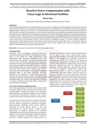
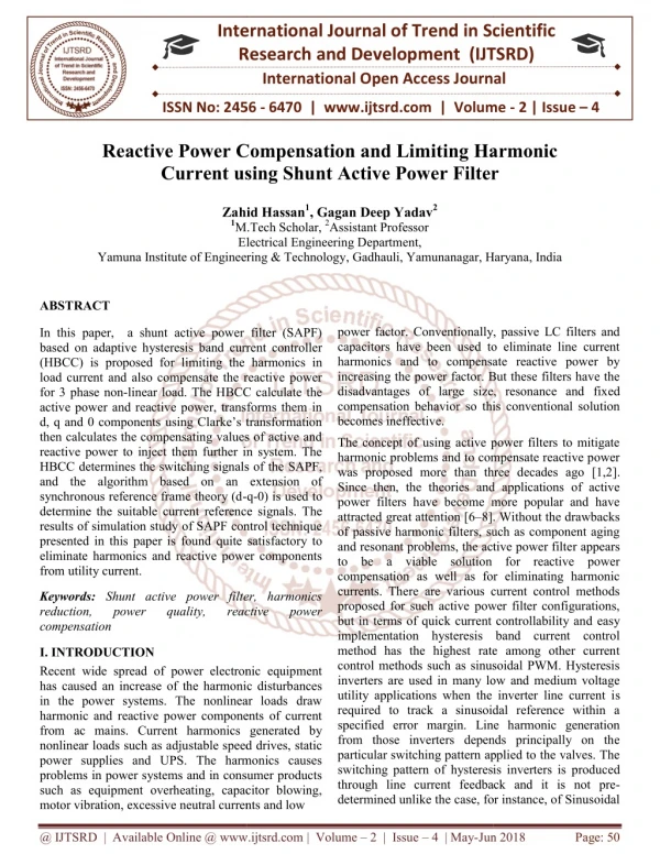
In this paper, a shunt active power filter SAPF based on adaptive hysteresis band current controller HBCC is proposed for limiting the harmonics in load current and also compensate the reactive power for 3 phase non linear load. The HBCC calculate the active power and reactive power, transforms them in d, q and 0 components using Clarke's transformation then calculates the compensating values of active and reactive power to inject them further in system. The HBCC determines the switching signals of the SAPF, and the algorithm based on an extension of synchronous reference frame theory d q 0 is used to determine the suitable current reference signals. The results of simulation study of SAPF control technique presented in this paper is found quite satisfactory to eliminate harmonics and reactive power components from utility current. Zahid Hassan | Gagan Deep Yadav "Reactive Power Compensation and Limiting Harmonic Current using Shunt Active Power Filter" Published in International Journal of Trend in Scientific Research and Development (ijtsrd), ISSN: 2456-6470, Volume-2 | Issue-4 , June 2018, URL: https://www.ijtsrd.com/papers/ijtsrd12958.pdf Paper URL: http://www.ijtsrd.com/engineering/electrical-engineering/12958/reactive-power-compensation-and-limiting-harmonic-current-using-shunt-active-power-filter/zahid-hassan<br>

E N D
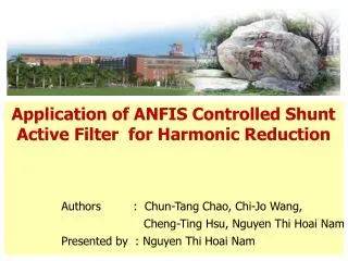
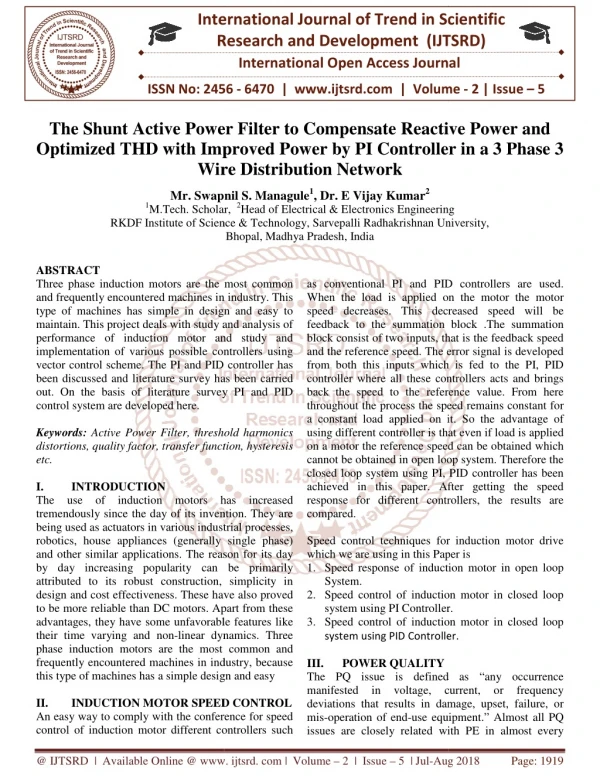
International Research Research and Development (IJTSRD) International Open Access Journal Compensation and Limiting Harmonic Current using Shunt Active Power Filter International Journal of Trend in Scientific Scientific (IJTSRD) International Open Access Journal ISSN No: 2456 ISSN No: 2456 - 6470 | www.ijtsrd.com | Volume www.ijtsrd.com | Volume - 2 | Issue – 4 Reactive Power C Current using S Harmonic ilter Zahid Hassan1, Gagan Deep Yadav2 M.Tech Scholar, 2Assistant Professor Zahid Hassan 1M.Tech Scholar, Electrical Engineering Electrical Engineering Department, Yamuna Institute of Engineering & Technology Yamuna Institute of Engineering & Technology, Gadhauli, Yamunanagar, Haryana Yamunanagar, Haryana, India ABSTRACT In this paper, a shunt active power filter (SAPF) based on adaptive hysteresis band current controller (HBCC) is proposed for limiting the harmonics in load current and also compensate the reactive power for 3 phase non-linear load. The HBCC calculate the active power and reactive power, transforms them in d, q and 0 components using Clarke’s transformation then calculates the compensating values of active and reactive power to inject them further in system. The HBCC determines the switching signals of the and the algorithm based on an extension of synchronous reference frame theory (d- determine the suitable current reference signals. The results of simulation study of SAPF control technique presented in this paper is found quite satis eliminate harmonics and reactive power components from utility current. power factor. Conventionally, passive LC filters and capacitors have been used to eliminate line current harmonics and to compensate reactive power by increasing the power factor. But these filters have the disadvantages of large size, resonance and fixed compensation behavior so this conventional solution becomes ineffective. r. Conventionally, passive LC filters and capacitors have been used to eliminate line current harmonics and to compensate reactive power by increasing the power factor. But these filters have the disadvantages of large size, resonance and fixed n behavior so this conventional solution In this paper, a shunt active power filter (SAPF) based on adaptive hysteresis band current controller (HBCC) is proposed for limiting the harmonics in load current and also compensate the reactive power linear load. The HBCC calculate the active power and reactive power, transforms them in d, q and 0 components using Clarke’s transformation then calculates the compensating values of active and reactive power to inject them further in system. The HBCC determines the switching signals of the SAPF, and the algorithm based on an extension of The concept of using active power filters to mitigate harmonic problems and to compensate reactive power was proposed more than three decades ago [1,2]. Since then, the theories and applications of active power filters have become more popular and have The concept of using active power filters to mitigate harmonic problems and to compensate reactive power was proposed more than three decades ago [1,2 Since then, the theories and applications of active power filters have become more popular and have attracted great attention [6–8]. Without the drawbacks of passive harmonic filters, such as component aging and resonant problems, the active power filte to be a viable solution for reactive power compensation as well as for eliminating harmonic currents. There are various current control methods proposed for such active power filter configurations, but in terms of quick current controllability an implementation hysteresis band current control method has the highest rate among other current control methods such as sinusoidal PWM. Hysteresis inverters are used in many low and medium voltage utility applications when the inverter line current i required to track a sinusoidal reference within a specified error margin. Line harmonic generation from those inverters depends principally on the particular switching pattern applied to the valves. The switching pattern of hysteresis inverters is produc through line current feedback and it is not pre determined unlike the case, for instance, of Sinusoidal determined unlike the case, for instance, of Sinusoidal -q-0) is used to determine the suitable current reference signals. The results of simulation study of SAPF control technique presented in this paper is found quite satisfactory to eliminate harmonics and reactive power components 8]. Without the drawbacks of passive harmonic filters, such as component aging and resonant problems, the active power filter appears to be a viable solution for reactive power compensation as well as for eliminating harmonic currents. There are various current control methods proposed for such active power filter configurations, but in terms of quick current controllability and easy implementation hysteresis band current control method has the highest rate among other current control methods such as sinusoidal PWM. Hysteresis inverters are used in many low and medium voltage utility applications when the inverter line current is required to track a sinusoidal reference within a specified error margin. Line harmonic generation from those inverters depends principally on the particular switching pattern applied to the valves. The switching pattern of hysteresis inverters is produced through line current feedback and it is not pre- Keywords: Shunt active power filter, harmonics reduction, power quality, compensation Shunt active power filter, harmonics power quality, reduction, reactive reactive power power I. INTRODUCTION Recent wide spread of power electronic equipment has caused an increase of the harmonic disturbances in the power systems. The nonlinear loads draw harmonic and reactive power components of current from ac mains. Current harmonics generated by nonlinear loads such as adjustable speed drives, static power supplies and UPS. The harmonics causes problems in power systems and in consumer products such as equipment overheating, capacitor blowing, motor vibration, excessive neutral currents and low motor vibration, excessive neutral currents and low Recent wide spread of power electronic equipment has caused an increase of the harmonic disturbances in the power systems. The nonlinear loads draw harmonic and reactive power components of current from ac mains. Current harmonics generated by ads such as adjustable speed drives, static power supplies and UPS. The harmonics causes problems in power systems and in consumer products such as equipment overheating, capacitor blowing, @ IJTSRD | Available Online @ www.ijtsrd.com @ IJTSRD | Available Online @ www.ijtsrd.com | Volume – 2 | Issue – 4 | May-Jun Jun 2018 Page: 50
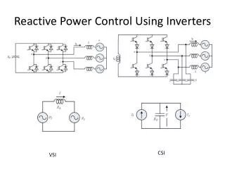
International Journal of Trend in Scientific Research and Development (IJTSRD) ISSN: 2456-6470 Pulse-Width Modulation (SPWM) where the inverter switching function is independent of the instantaneous line current and the inverter harmonics can be obtained from the switching function harmonics. As in most PWM applications the interval between two consecutive switching actions varies constantly within a power frequency cycle. It means that the switching frequency is not constant but varies in time with operation point and conditions. In principle increasing inverter operation frequency helps to get a better compensating waveform. However there are device limitations and increasing the switching frequency cause increasing switching losses, audible noise and EMF related problems. The range of frequencies used is based on a compromise between these two different factors. In this paper, the control of switching frequency is realized by introducing a hysteresis band current control algorithm. The main aim of this study is to reduce the THD of supply current and switching frequency of APF. The hysteresis band current controller changes the hysteresis bandwidth as a function of reference compensator current variation to optimize switching frequency and THD of supply current. In this paper, the synchronous d-q-0 reference frame theory is first briefly reviewed. Next, the proposed hysteresis band current control based compensation strategy for the three-phase active power filter is described. Then, simulation results are presented followed by the conclusion. In a SAPF depicted in Fig. 1, a current controlled voltage source inverter is used to generate the compensating current (ic) and is injected into the utility power source grid. This cancels the harmonic components drawn by the nonlinear load and keeps the utility line current (is) sinusoidal. A variety of methods are used for instantaneous current harmonics detection in active power filter such as FFT (fast Fourier technique) technique, instantaneous p-q theory, synchronous d-q reference frame theory or by using suitable analog or digital electronic filters separating successive harmonic components. In this paper, the synchronous d-q-0 reference frame theory based algorithm is proposed. III. D-Q-0 REFERENCE FRAME BASED COMPENSATION The three phase load currents have already been transformed to the synchronous reference frame (a-b-c to d-q-0 transformation). A high pass filter is used to extract the dc component fundamental frequency of the currents. The coordinate transformation from three-phase load currents (iLa, iLb, iLc) to the synchronous reference frame based load currents (iLd, iLq, iL0) is obtained as follows: representing the t 2 /3 2 /3 2 /3 cos t cos t cos t Ld i i i i i La 2 sin sin t sin t + 2 /3 Lq Lb i 3 1/ 2 1/ 2 1/ 2 L 0 Lc II. SHUNT ACTIVE POWER FILTER (SAPF) The shunt active power filter (SAPF) is a device that is connected in parallel to and cancels the reactive and harmonic currents from a nonlinear load. The resulting total current drawn from the ac main is sinusoidal. Ideally, the SAPF needs to generate just enough reactive and harmonic current to compensate the nonlinear loads in the line. The dc side voltage of SAPF should be controlled and kept at a constant value to maintain the normal operation of the inverter. Because there is energy loss due to conduction and switching power losses associated with the diodes and IGBTs of the inverter in APF, which tend to reduce the value of Vdc across capacitor Cdc. A feedback voltage control circuit needs to be incorporated into the inverter for this reason. The difference between the reference value, Vref and the feedback value (Vdc), an error function first passes a PI regulator and the output of the PI regulator is subtracted from the d axis value of the harmonic current components. Synchronous d-q-0 reference frame based compensation algorithm determined negatives of the outputs of the inverse transformation matrix (d-q-0 to a-b-c). IV. HYSTERESIS BAND CURRENT CONTROLLER The hysteresis band current control technique has proven to be most suitable for all the applications of current controlled voltage source inverters in active power filters. The hysteresis band current control is Fig. 1. Basic principle block diagram of a 3-phase SAPF @ IJTSRD | Available Online @ www.ijtsrd.com | Volume – 2 | Issue – 4 | May-Jun 2018 Page: 51
International Journal of Trend in Scientific Research and Development (IJTSRD) ISSN: 2456-6470 characterized by unconditioned stability, very fast response, and good accuracy [4,5]. On the other hand, the basic hysteresis technique exhibits also several undesirable features; such as uneven switching frequency that causes acoustic noise and difficulty in designing input filters [10]. The conventional hysteresis band current control scheme used for the control of active power filter line current is shown in Fig. 2, composed of a hysteresis around the reference line current. The reference line current of the active power filter is referred to as Ic∗and actual line current of the active power filter is referred to as Ic. The hysteresis-band current control method is popularly used because of its simplicity of implementation, among the various PWM techniques. Besides fast-response current loop and inherent-peak current limiting capability, the technique does not need any information about system parameters. However, the current control with a fixed hysteresis band has the disadvantage that the switching frequency varies within a band because peak-to-peak current ripple is required to be controlled at all points of the fundamental frequency wave [3]. But interesting improved versions of this technique are presented in literature [9,10]. V. SIMULATION RESULTS AND DISCUSSIONS In conventional fix band hysteresis current control and hysteresis band current control method, instantaneous P0, P and Q are shown in Fig. 3, respectively. In practical application, it is necessary to kept switching frequency to a certain limits, in order to determine switching device and its switching losses. In a hysteresis band current controller, switching frequency remains constant respecting the system parameters and defined frequency. Fig. 2. Conventional hysteresis band current controller. The hysteresis band current controller decides the switching pattern of active power filter [11]. The switching logic is formulated as follows: If ica < (ica* − HB) upper switch is OFF and lower switch is ON for leg “a” (SA=1). The compensation by APF is implemented in a three- phase power system which the utility power supply voltage of 50 V and current source three-phase diode- bridge rectifier with resistive load as the harmonic current compensation specifications and the circuit parameters used in the simulation are indicated in Table 1. harmonic current and reactive power If ica > (ica* + HB) upper switch is ON and lower switch is OFF for leg “a” (SA = 0). The switching functions SB and SC for phases B and C are determined similarly, using corresponding reference and measured currents and hysteresis bandwidth (HB). object. The design Table 1 Design specifications and circuit parameters The switching frequency of the hysteresis band current control method described above depends on how fast the current changes from the upper limit of the hysteresis band to the lower limit of the hysteresis band, or vice versa. The rate of change of the actual active power filter line currents vary the switching frequency, therefore the switching frequency does not remain constant throughout the switching operation, but varies along with the current waveform. Furthermore, the line inductance value of the active power filter and the dc link capacitor voltage are the main parameters determining the rate of change of active power filter line currents. The switching frequency of the active power filter system also depends on the capacitor voltage and the line inductances of the active power filter configuration. Switching frequency Rectifier side inductance Fundamental frequency Cdc capacitor AC supply Inverter dc voltage (Vdc) Rectifier load resistance Rectifier load inductance 20 MHz 1 mh 50 Hz 4700 µF 50 V RMS 130 V 25 ohm 0.5 mh @ IJTSRD | Available Online @ www.ijtsrd.com | Volume – 2 | Issue – 4 | May-Jun 2018 Page: 52
International Journal of Trend in Scientific Research and Development (IJTSRD) ISSN: 2456 Scientific Research and Development (IJTSRD) ISSN: 2456 Scientific Research and Development (IJTSRD) ISSN: 2456-6470 Fig. 3 Waveforms for P Fig. 3 Waveforms for P0, P and Q Fig. 4 Waveforms for Load current, compensating current, source current and load voltage Fig. 4 Waveforms for Load current, compensating current, source current and load voltage Fig. 4 Waveforms for Load current, compensating current, source current and load voltage The load current, source current, compensating current and load voltage three phase waveform are illustrated in Fig. 4 and demonstrates that controller can exactly keep track the harmonic current components. From the Fig. 4 it is found that the current drawn from the source is sinusoidal while the load current, due to the nature of the load is non sinusoidal. The SAPF injects compensating current in to the system such that the current drawn from the source is sinusoidal so that the other devices and components connected to the system not get affected. The utility power source current after the harmonic compensation has some harmonics components but these can be ignored as per the IEEE standards. The THD (total harmonic distortion) is also computed in load current as well as in supply current. The THD is 21.88% before harmonic compensation in load is 21.88% before harmonic compensation in load The load current, source current, compensating current and load voltage three phase waveform are illustrated in Fig. 4 and demonstrates that controller can exactly keep track the harmonic current components. From the Fig. 4 it is found that the wn from the source is sinusoidal while the load current, due to the nature of the load is non- sinusoidal. The SAPF injects compensating current in to the system such that the current drawn from the source is sinusoidal so that the other devices and nts connected to the system not get affected. The utility power source current after the harmonic compensation has some harmonics components but these can be ignored as per the IEEE standards. The THD (total harmonic distortion) is also computed current as well as in supply current. The THD current and 4.48% in supply current after harmonic current compensation that is within the limit of the harmonic standard of IEEE 519. The performance of sed hysteresis band current controller regarding harmonics cancellation is compared with a fixed band current controller. Harmonic spectrum of the nonlinear load current is shown in Fig. 10. Harmonic spectrum of the source current with the ed band hysteresis current controllers are shown in Figs. 11 and 12, respectively. There is no difference between adaptive hysteresis band current controller and fixed band controller for current and 4.48% in supply current after harmonic current compensation that is within the limit of the harmonic standard of IEEE 519. The performance of the proposed hysteresis band current controller regarding harmonics cancellation is compared with a fixed band current controller. Harmonic spectrum of the nonlinear load current is shown in Fig. 10. Harmonic spectrum of the source current with the proposed and fixed band hysteresis current controllers are shown in Figs. 11 and 12, respectively. There is no difference between adaptive hysteresis band current controller and fixed band controller for distortion spectrum. Conclusions This paper demonstrates the validit hysteresis band current controller for active power hysteresis band current controller for active power This paper demonstrates the validity of the proposed @ IJTSRD | Available Online @ www.ijtsrd.com @ IJTSRD | Available Online @ www.ijtsrd.com | Volume – 2 | Issue – 4 | May-Jun Jun 2018 Page: 53
International Journal of Trend in Scientific Research and Development (IJTSRD) ISSN: 2456-6470 5)J. Holtz, Pulsewidth modulation for electronic power conversion, Proc. IEEE 82 (8) (1994) 1194–1214. filters. The verification of the control system is being performed and test results will be reported in the future papers. The results of simulation study of APF control technique presented in this paper is found quite satisfactory to eliminate harmonics and reactive power components from utility current. The shunt active power filter (SAPF) presented in this paper for the compensation of harmonic current components in nonlinear load was effective for harmonic isolation and keeping the utility supply line current sinusoidal. 6)J.S. Tepper, W. Juan, J.W. Dixon, A simple- frequency independent method for calculating the reactive and harmonic current in a nonlinear load, IEEE Trans. Ind. Electron. 43 (6) (1996). 7)H. Akagi, et al., Instantaneous reactive power compensation comprising switching devices without energy components, IEEE Trans. Ind. Appl. 20 (3) (1984). References 1)W.M. Grady, M.J. Samotyj, A.H. Noyola, Survey of active power line conditioning methodologies, IEEE Trans. Power Delivery 5 (3) (1990) 1536– 1542. 8)Nakata, A. Ueda, A. Torii, A method of detection for an active power filter applying moving average to pq-theory, IEEE PESC 98 Record. 9)S. Buso, L. Malesani, Comparison of current control techniques for active filter applications, IEEE Trans. Ind. Electron. 45 (5) (1998). 2)H. Akagi, New trends in active filter for improving power quality, in: Proceedings of the 1996 International Electronics, Drives and Energy System for Industrial Growth. Conference on Power 10)S. Buso, S. Fasolo, L. Malesani, P. Mattavelli, A dead beat adaptive hysteresis current control, IEEE Trans. Ind. Appl. 36 (4) (2000) 1174–1180. 3)B.K. Bose, An adaptive hysteresis band current control technique of a voltage feed PWM inverter for machine drive system, IEEE Trans. Ind. Electron. 37 (5) (1990) 402–406. 11)B. Singh, K. Haddad, A. Chandra, A new control approach to threephase active filter for harmonics and reactive power compensation, IEEE Trans. Power Syst. 13 (1) (1998) 133–138. 4)J. Holtz, Pulse width modulation – a survey, IEEE Trans. Ind. Electron. 39 (5) (1992) 410–420. @ IJTSRD | Available Online @ www.ijtsrd.com | Volume – 2 | Issue – 4 | May-Jun 2018 Page: 54