Bipolar Junction Transistor Forward Current Gain Digital Meter
Bipolar Junction Transistor Forward Current Gain Digital Meter. Group Members Amel Ahmed 980723636 Deema Omar 980424894 Mona Abdulla 980723631 Nada Ahmed 980723521 Sahar Khalid 980723832. Advisor. Dr. Jihad Mohaidat . Presentation Outline. Objectives. Methods .

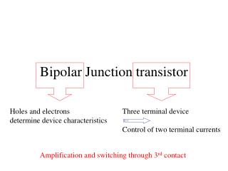
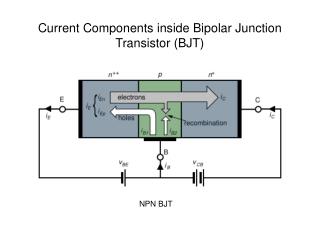
Bipolar Junction Transistor Forward Current Gain Digital Meter
E N D
Presentation Transcript
Bipolar Junction Transistor Forward Current Gain Digital Meter Group Members Amel Ahmed 980723636 Deema Omar 980424894 Mona Abdulla 980723631 Nada Ahmed 980723521 Sahar Khalid 980723832 Advisor Dr. Jihad Mohaidat
Presentation Outline Objectives. • Methods. • Background Theory. • Results & Discussion. • Block Diagram. • Project Impact. • Flow Chart. • Conclusion.
Objectives • To design a digital meter that measures the Bipolar Junction Transistor Forward Current Gain (β). • Easy and convenient way to measure β comparing with the curve tracer.
VCC RB RC IC VCE IB VBE IE Background Theory Specifications 1 mA < IC < 10 mA 3 V < VCE < 12 V 50 < β < 300
Microcontroller Definition A small Computer, , containing the CPU, code memory, data memory and peripheral I/O. Characteristics of the PIC16F877 • It’s a FLASH programmable device. • Built-in Analog to Digital conversion circuitry. • Built-in EEPROM. • Supported by various programming languages.
IC IC RC RC IB IB RB RB IE IE Voltage Polarity Detection NPN PNP 15V -15V 15V VCE VCE
4×4 keypad matrix Row connector Column connector Keypad Principles
1 5V GND 2 Contrast adjustment voltage 3 Register select signal 4 Read/write select signal 5 Operation enable signal 6 Data bus 7-14 Liquid Crystal Display The LCD is a smart device, which is used to display the output visual information.
Relays Types of the Relay • Normally Open • Normally Closed
Relays Types of theRelay • Switching Relay
Methods Assembly Language PicBasic Language • High Level Language • Portable from one device to another • Single instruction allows you to perform a complete task
Methods Important statements for LCD LCD_OUT
Methods Keypad Statements
Methods Mathematical Operations Statements
Methods Mathematical Operations Statements
Flow Chart Results & Discussion START Is BJT NPN OR PNP?? YES NO Change Polarity Enter Values of VCE & IC
Results & Discussion Compare between IC & ICQ POSITIVE ZERO Decrease value of RC NO EQUAL ? YES
Results & Discussion Control RB ZERO Compare Between IC & ICQ Different very small ? NO YES Record IC & IB Calculate B and Display it STOP
PORT A PORT B PORT E PORT D PORT C Results & Discussion
Results & Discussion LCD Connection
Results & Discussion Keypad Connection
Results & Discussion Relay & Voltage Polarity Connections
Results & Discussion Design of Resistors Banks Find the acceptable values of collector and base conductance that can meet the specifications. • Rb • 7 resistors • Rc • 6 resistors
Rc Rb Results & Discussion Design of Resistors Banks
Results & Discussion Relays Circuit
R2 R1 VO1 Vi1 Results & Discussion Op-Amp Circuit • Op – Amp importance : Guarantee the acceptable voltage range to the ADC. • Gain of Op – Amp 1:
R2 R R1 R VO2 Vi1 Results & Discussion Gain of Op – Amp 2: Overall Gain:
Results & Discussion • R1 = 3 M • R2 = 1 M • R = 1 M Gain of Op – Amp 1: Gain of Op – Amp 2:
Results & Discussion Overall Gain:
Results & Discussion Percentage error:
R4 R2 1M 1M V4 V2 15V 15V R3 R1 U1 1M + 3M + OPAMP5 U2 + V1 OPAMP5 15V V5 V3 -15V -15V Results & Discussion
Results & Discussion Vo1:
Results & Discussion Vo2:
Results & Discussion Basic Pro programs • Program 1: Keypad controlling. • Program 2: Liquid Crystal Display controlling. • Program 3: Interfacing program between Keypad & LCD. • Program 4: Testing Microcontroller Mathematical operation.
Project Impact • The project does not have any bad impact on the environment because it will not cause any damages, hazard, or pollution in the surrounding area. • The technology developed in this project can be used to protect the environment, for example design a microcontroller based system to monitor the pollution in the air, or oil contents in the water.
Conclusion Problems Faced • Software. (Assembly Language, Basic Pro) • Budget. ( Not Available) • Components. (Lab-X1 Board)