Download
1 / 27
270 likes | 378 Vues
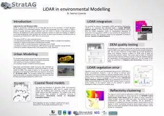
Light Transport and Detection with VLPCs. Dipangkar Dutta TUNL/ Duke University MEP group. Current Conceptual Design. Light Transport to PMTs. C. R. Brome et al., PRC 63, 055502 (2001). Visible Light Photon Counters.

E N D
Light Transport and Detection with VLPCs Dipangkar Dutta TUNL/ Duke University MEP group
Light Transport to PMTs C. R. Brome et al., PRC 63, 055502 (2001)
Visible Light Photon Counters VLPC's are arsenic doped silicon diodes,designed to convert single photons in to many thousands of electrons with high quantum efficiency • Detects single photons • Operate at a few degrees Kelvin • Quantum efficiency ~80% • Insensitive to magnetic fields • High gain ~40 000 electrons per converted photon
Visible Light Photon Counters Excellent individual photoelectron resolution Low gain dispersion ~0.13 p.e. Integrated Charge
Visible Light Photon Counters 1400 1200 1000 800 Frequency 600 400 200 0 0 10 20 30 40 50 60 70 80 Gain (in Thousands) 60 000 20 000 Ideal operating temperature ~ 6.5 K High gain ~ 20,000- 60,000 S. Takeuchi et al., Appl. Phys. Lett, 74, 1063 (1999)
VLPC Applications Extensively used in Scintillating Fiber Trackers @ Fermilab Fermilab has 10+ yrs of experience and expertise
VLPC Applications Asst. Prof. at Duke EE dept, (developed new cheap cold amplifiers for VLPCs) Ex TUNL, borrowed couple of bare VLPC chips from him
The Issues • Shorter pathlength from cell to detector • No breaks in the light guide. • lower backgrounds • Light collected in the cell could be smaller • No previous experience, unlike the light guides.
Studies by nEDM Collaborators Wavelength shifting fiber based detector was tested by the Doyle group for their neutron traps. D. N. McKinsey et al., NIM A 516,475 (2004)
Studies by nEDM Collaborators The Doyle group also attempted to test wavelength shifting fiber based detector with VLPCs instead of PMTs. J. S. Butterworth et al., Private Communication VLPC, wavelength shifting fiber, pre-amplifier board and biasing circuit borrowed from Fermilab. “Failed to get the pre-amp board working, it was too noisy.” - James Butterworth
New Readout Method Use a ultra low-noise amplification scheme developed for single photon counting experiments J. Kim et al., Appl. Phys. Lett, 70, 2852 (1997) S. Takeuchi et al., Appl. Phys. Lett, 74, 1063 (1999)
Test Setup at Duke Summer 2005 by REU student Amber Nelson
New Readout Method Warm Amp
The Early Tests • No signal detected (not even dark counts) • Excessive noise. Do the VLPC chips still work after so many years? The test was simplified to detect just the signal from dark counts After several unsuccessful attempts, we loaned the VLPC chips to Prof. Jungsang Kim of the Duke EE Department to test them in his apparatus.
Jungsang Kim’s Apparatus To warm Amplifier To Vacuum pump Cold Amplifier VLPC Signal was seen immediately, VLPC chips were not broken!!
Bare-bones Test Setup Fall 2005 –Spring 2006 Duke Undergrad Alvaro Chavarria
Bare-bones Test Setup A spectrum analyzer was used to determine all sources of noise A low pass filters was added to all inputs and outputs
First Signal 15.0 10.0 5.0 Voltage (mV) 0.0 -5.0 Observed in Prof. Kim’s Lab
First Signal (Repeat) Repeated in our lab
The New Setup (cell test) May 2006
The New Setup (cell test) May 2006 Once again in this new setup noise is too high to even see the dark counts.
The Next Step May 2006 Replace G10 tube with metal tube and repeat
The Final Steps • Re-establish the dark count signal in the new setup. • Look for changes in the signal when an Am241 source is lowered into the dTPB coated cell. • Tests to be performed over the next few weeks. Vince and Yuri will come up to Duke to test their silicon photo multipliers coupled to the fiber cell.