Concrete Test Section RPF Overview: Evaluation of Low-Volume Pavement Performance
This document outlines the objectives, design details, material properties, instrumentation, traffic conditions, and construction methods of the Concrete Test Section RPF conducted in May 2002. The objectives include calibrating risk at lower traffic volumes and quantifying the failure of low-volume concrete pavements. The project involved multiple parties, including the Cement and Concrete Institute, CSIR Transportek, and the University of Pretoria. The report presents comprehensive details on various section designs, materials used, and the ongoing observations concerning performance and distress in the pavements.

Concrete Test Section RPF Overview: Evaluation of Low-Volume Pavement Performance
E N D
Presentation Transcript
Concrete Test Section RPF 8 May 2002
Outline • Objectives • Design details • Material properties • Instrumentation • Traffic • Construction • Conclusion
Objectives • To calibrate cncRisk at the lower end of the traffic spectrum • To quantify failure of low-volume concrete pavements
Parties • Cement and Concrete Institute • CSIR Transportek • University of Pretoria • Alpha Stone and Readymix • BKS • Raubex
Design details • University of Pretoria • Section 1 • 75 mm SFRC (30 kg/m3) Joint spacing 3 m • 140 mm Foam concrete subbase • In situ • Section 2 • 75 mm SFRC (30 kg/m3) Joint spacing 6 & 4 m • 125 mm CTS • In situ
Design details • University of Pretoria (cont) • Section 3 • 75 mm SFRC (30 kg/m3) No joints • 25 mm ETB • 125 mm CTS • In situ
Design details • CSIR Transportek • Section 4 • 50 mm “CRCP” • 50 mm ETB • 125 mm CTS • In situ • Section 5 • 75 mm “CRCP” • 25 mm ETB • 125 mm CTS • In situ
Design details • CSIR Transportek • Section 6 • 100 mm “CRCP” • 125 mm CTS • In situ
Design details • C&CI • Section 7 • 100 mm butt jointed Joint spacing 2 and 3 m • 125 mm CTS • In situ • Section 8 • 100 mm butt jointed Joint spacing 2 and 3 m • 40 mm continuously graded asphalt • 100 mm CTS • In situ
Design details • C&CI • Section 9 • 140 mm jointed Joint spacing 2, 3 and 4 m • 125 mm gravel • In situ • Section 10 • 140 mm butt jointed Joint spacing 2, 3 and 4 m • 125 gravel • In situ
Design details • C&CI • Section 11 • 140 mm dowel jointed Joint spacing 2, 3 and 4 m Dowels 25 mm @ 300 c/c • 125 mm gravel • In situ
Material Properties • In situ • CBR 80 • Quartzitic gravel A-1-a G5/G6 • Compaction 97% Mod. AASHTO • FWD deflections 1,0 mm
Material Properties • Subbase • As in situ • Compaction 97% Mod. AASHTO • Stabilized with 2% CEM I 42.5 (C3) (Recycler) • UCS 2000 kPa • FWD deflection 0,9 mm and Stab 0,5 mm
Material Properties • ETB • Subbase material • Stabilized with 1,5% anionic stable grade 60%, 1% cement • Asphalt • Continuously graded hot mix with 60/70 pen • 12 mm aggregate size
Material Properties • Concrete • Strength • fc 22 - 42 MPa • ff 3,7 - 5,6 MPa • Mod E 24 - 33 GPa • Shrinkage 0,05 - 0,06 % • Cement CEM I 42,5/GGBS 80/20
Instrumentation • LVDT’s • Centre • Side • Thermocouples • Conventional • Programmable • MDD’s • Weather station
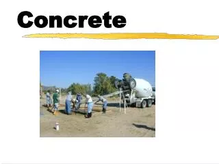
Construction • Readymix concrete • Compaction by poker and beam • Curing compound • Plastic sheeting
Traffic • Trucks leaving quarry • Weighbridge data • No of axles • Approximately 300 E80’s per day • To date 14 000 E 80’s
Observations • Very little distress to date • Vertical movement at joints under traffic but no relative movement • Rocking of slabs on foam concrete • Some corner breaks • Plastic shrinkage cracks not affecting performance
Future • Ongoing observations • Continual recording of instruments to end May • Panel to define failure • Analysis of results • Availability of data