Heating, Ventilation, and Air Conditioning
CHAPTER. Heating, Ventilation, and Air Conditioning. 1. Instructor Name: (Your Name). Learning Objectives. Describe the evolution of the modern-day air-conditioning system. Explain the purpose of the compressor. Describe the function of the condenser.

Heating, Ventilation, and Air Conditioning
E N D
Presentation Transcript
CHAPTER Heating, Ventilation,and Air Conditioning 1 Instructor Name:(Your Name)
Learning Objectives • Describe the evolution of the modern-day air-conditioning system. • Explain the purpose of the compressor. • Describe the function of the condenser. • Explain the key differences between an orifice tube and a thermostatic expansion valve.
Learning Objectives(continued) • Explain the purpose of a drier. • Describe the function of the evaporator. • Explain how the accumulator works and its function. • Describe the uses for the manifold gauge set.
Learning Objectives(continued) • List the different types of leak detectors and explain their purpose. • Explain the functions of a vacuum pump. • Outline the reasons for refrigerant recovery. • Describe refrigerant recycling.
Learning Objectives(continued) • Explain why antifreeze must be recycled. • List the advantages of a ventilation system. • Outline the advantages of using a scan tool. • Explain why a refrigerant identifier should be used before servicing an air-conditioning system.
Introduction • We have come a long way in a brief time period regarding the development of climate control systems in modern vehicles. • A technician must understand what functions a heating, ventilation, and air conditioning (HVAC)system performs and how it accomplishes these tasks.
Introduction(continued) • A technician must also recognize the components of a modern HVAC system and the tools required to maintain them.
System Overview In this chapter, you will learn about: • The history of the modern HVAC system. • The purpose of the heating, ventilation, and air-conditioning system. • The components that make up modern HVAC systems. • Some of the specialty tools used by technicians in the HVAC field.
History ofAir Conditioning • People tried to control the temperature of their environment as far as the Egyptian pharaohs. • In 1884, William Whiteley placed blocks of ice in a tray under a horse carriage and used a fan attached to a wheel to force air inside. • Later, a bucket of ice in front of a floor vent became the automotive equivalent.
History of Air Conditioning (continued) • Automobiles were not very comfortable for passengers in the early years because the cabins were open. • Eventually, car companies began to close up the passenger cabins, which required a change in temperature control systems. • At first, vents were put in the floors of cars, bringing in more dirt and dust than cool air.
History of Air Conditioning(continued) • In 1939, Packard produced the first passenger cars using refrigeration components. A huge evaporator was mounted in the trunk. • Cadillac introduced an air-conditioned car in 1941. • In 1954, Delphi Harrison Thermal Systems introduced an air-conditioning system that located all the major components under the car’s hood (Figure 1-1).
History of Air Conditioning (continued) Figure 1-1.A 1939 Packard with air conditioner.
Today’s Air-Conditioning Systems • Today’s vehicles are very comfortable no matter what the weather is like outside. • Innovations and improvements in overall durability have increased the complexity of today’s air-conditioning systems. • As today’s truck drivers travel through different regions, they can enjoy the same comfort levels as they do at home. • Climate-control systems automatically make the transition from heating to cooling and back.
Today’s Air-ConditioningSystems(continued) • For vehicles operating in the northern U.S. or Canada, heating systems keep occupants warm and comfortable and help keep the windshield clear of ice and snow. • For those operating in the southern U.S. or Canada, air conditioning greatly improves the comfort level of the occupants. • An added benefit of air conditioning systems is that they remove humidity from the circulating air.
Today’s Air-ConditioningSystems(continued) • The ‘‘do it yourself’’ approach to air-conditioning repair is a thing of the past. • Technicians today must work within stringent environmental regulations. • The technician must be certified to purchase refrigerant and to repair air-conditioning systems. • Repair shops must have equipment that can remove all refrigerant from a vehicle to prevent ozone-depleting chemicals from escaping into the air.
Vehicle Heat andCold Sources • The heat and cold that an HVAC system must overcome originates from many different sources. • Ambient air temperature and solar radiation are two such sources. • Tinting of windows can reduce the effects of solar radiation.
Vehicle Heat andCold Sources (continued) • Other heat sources are those generated by the engine and cooling system. These include transmission heat, exhaust system heat, and heat radiated up through the floor of the vehicle. • Human body heat and warm moist air from breathing constantly radiate into the air in the cab. • All add to the heat and moisture that must be removed by an HVAC system (Figure 1-2).
Vehicle Heat andCold Sources(continued) Figure 1-2. Heat enters the cab through windows. Engine heat enters through the firewall, and heat radiates up through the floor of the vehicle.
Vehicle Heat andCold Sources(continued) • Another source of hot or cold air is the fresh air ventilationsystem. Air is circulated by a fan, usually referred to as a blower motor. • Outside air coming into the cab must either be heated or cooled before it reaches the vehicle interior. • The ventilation system improves the performance of the air-conditioning or heating system by improving air flow within the vehicle.
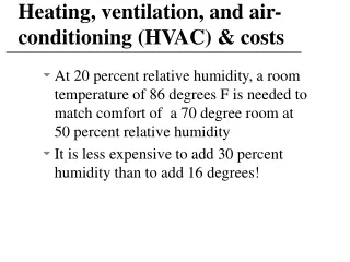
Purpose of theHVAC System HVAC systems perform three very important functions: • Temperature control. The HVAC maintains the temperature within the passenger compartment as selected by the operator. • Humidity control. The HVAC system reduces the humidity within the passenger compartment. • Air circulation control. The HVAC refreshes the air in the vehicle’s interior.
Air-Conditioning Components The most common components of truck air-conditioning systems are: Evaporator Receiver-drier Accumulator • Compressor • Condenser • Pressure regulating devices: • Orifice tube • Thermostatic expansion valve
Compressor • The compressorcan be referred to as the heart of the HVAC system. • Compressors are bolted to the engine and are belt-driven by either a V-belt or a serpentine belt. • The compressor is responsible for compressing and transferring refrigerant gas (Figures 1-3 and 1-4).
Compressor(continued) Figure 1-3.Swash plate compressor.
Compressor(continued) Figure 1-4. Two-piston type compressor.
Compressor(continued) • The air-conditioning system may be divided into two different sides: the high-pressure (discharge) side and the low-pressure (suction) side. • The compressor is the dividing point between the suction and discharge sides of the air-conditioning system.
Compressor(continued) • The suction side of the compressor draws in refrigerant gas from the outlet of the evaporator. • Once refrigerant is drawn into the suction side, it is compressed, which concentrates the heat in the vapor, raising its temperature. • The vapor leaving the compressor must be hotter than the atmosphere so that, while it is in the condenser, it will dissipate the heat that it carries to the cooler ambient air.
Condenser • The condenserdissipates the heat that was once inside the cab of the truck. • The condenser is designed to radiate heat, and it is usually located in front of the radiator. • In some retrofit applications, it may be located on the cab roof (Figure 1-5).
Condenser (continued) Figure 1-5.Refrigerant surrenders heat from the cab to the ambient air in the condenser.
Condenser(continued) • Condensers must have air flow any time the system is in operation. This is accomplished by the ram air effect or by the engine cooling fan. • The compressor pumps hot refrigerant gas into the top of the condenser. • The gas is then cooled and condenses into high-pressure liquid refrigerant at the bottom of the condenser or condenser outlet.
Pressure Regulating Devices The desired temperature of an evaporator is maintained by controlling refrigerant pressure. Two pressure-regulating devices are: • Orifice Tube. This is a simple restriction located in the liquid line between the condenser outlet and the evaporator inlet (Figure 1-6). • Thermostatic Expansion Valve (TXV).The TXV’s job is to regulate the flow of refrigerant so that any liquid refrigerant metered through it has time to evaporate or change states from liquid to gas before leaving the evaporator (Figure 1-7).
Pressure RegulatingDevices (continued) Figure 1-6. An orifice tube is used to meter the flow of refrigerant into the evaporator of an orifice tube air-conditioning system.
Pressure RegulatingDevices (continued) Figure 1-7.An assortment of thermostatic expansion valves.
Evaporator • The evaporator’s primary function is to remove heat from within the cab of the vehicle. It is also used for dehumidification. • It is usually located within the controlled space or is in some way isolated from the outside of the vehicle. • A blower motor circulates air from the cabin through the evaporator coil.
Evaporator (continued) • As the warmer air travels through the cooler fins of the evaporator, the moisture in the air condenses on their surface. • In order to keep the evaporator from freezing, several different temperature- or pressure-regulating devices may be used. • Keeping the evaporator from freezing is extremely important because a frozen evaporator will not absorb very much heat (Figure 1-8).
Evaporator (continued) Figure 1-8. The evaporator is the component that absorbs heat from the truck’s cab.
Evaporator (continued) • Refrigerant enters the evaporator as a low-pressure liquid. • The refrigerant temperature is lower than that of the air inside the cab, and heat flows from a warm substance to a cooler one. • The warm air from the cabin passes through the evaporator fins and causes the liquid refrigerant in the evaporator to boil.
Evaporator (continued) • The boiling refrigerant absorbs large quantities of heat from the cabin. • This heat is then carried off with the refrigerant to the outside of the vehicle. • The force that draws this low-pressure refrigerant through the evaporator is the suction effect of the compressor.
Receiver-Drier • The receiver-drier is used in air-conditioning systems with a TXV. • It is used to store refrigerant and separate any gas refrigerant from liquid refrigerant. • It is a cylindrical metal container usually located on the bulkhead. • The TXV requires liquid refrigerant to operate efficiently. • The receiver and desiccant types are chosen for the type of system and refrigerant used within the system (Figure 1-9).
Receiver-Drier(continued) Figure 1-9.The receiver-drier provides storage filtration and moisture removal for passing refrigerant.
Accumulator • An accumulatoris used in systems that employ a fixed orifice tube to control the flow of refrigerant into the evaporator. • The accumulator prevents liquid refrigerant from reaching the compressor. • It is plumbed into the system between the exit of the evaporator and the inlet of the compressor. • It also contains a desiccant that removes debris and moisture from the passing refrigerant (Figure 1-10).
Accumulator(continued) Figure 1-10. The accumulator ensures that only vaporous refrigerant may be returned to the compressor.
Special Air-Conditioning Tools • To service air-conditioning systems, technicians must be familiar with the use of tools designed specifically for the mobile air-conditioning field. • One of the tools that must be mastered by any air-conditioning or refrigeration technician is the manifold gauge set.
Manifold Gauge Set • A technician must be able to read the manifold gauge set and interpret the pressures of the air-conditioning system as it operates. • These pressures tell the technician if the system is operating correctly or if there is a problem. • The manifold gauge set is usually the first tool installed on an air-conditioning system before any diagnostic work takes place.
Manifold Gauge Set(continued) • A manifold gauge set consists of a manifold block, two hand valves, three refrigerant hoses, and two pressure gauges (Figure 1-11). • The refrigerant hoses are usually color-coded to indicate where they should be connected. • The hose on the left is color-coded blue and is connected to the low-pressure/suction side of an air-conditioning system. • A gauge that reads either vacuum or pressure is connected to the low-pressure hose through the manifold and is also usually blue.
Manifold Gauge Set (continued) Figure 1-11. A manifold gauge set is probably the technician’s best diagnostic tool.
Manifold Gauge Set(continued) • Because the gauge reads in two different ranges of pressure, it is usually referred to as a compound gauge. • On the vacuum side, the gauge will read to 30 inches of mercury. • On the positive pressure side, the gauge will read accurately up to 120 psi with a retard section of the gauge reading up to 250 psi. • Pressures from 120 psi to 250 psi can’t be measured accurately, but they will not damage the gauge.
Manifold Gauge Set(continued) • The hose on the right side of the gauge set is color-coded red. It is connected to the high-pressure/ discharge side of the air-conditioning system. • A gauge that reads in psi or kilopascals is connected to the high-pressure hose through the manifold. • This gauge is usually red, like the hose to which it is connected. • The high side is usually calibrated from 0 psig (0 kPa) to 500 psig (3447 kPa). • This is usually referred to as the high-pressure gauge.
Safety Eyewear • Safety eyewear should be worn any time a person enters a shop environment! • This is especially true when working with refrigerants. • Full face shields are available for technicians working on air-conditioning systems. • The safety eyewear worn by the technician should be a type that is approved for working with liquids or gases and must meet ANSIZ87.1-1989 standards (Figure 1-12).
Safety Eyewear Figure 1-12. Safety eyewear, glasses, goggles, or shields should be worn by everyone entering the shop.
Leak Detectors • The purpose of a leak detector is to determine the origin of a refrigerant leak. • Special tools are required to find refrigerant leaks because often the gas will escape, leaving no visible trace as to where it exited the system (Figure 1-13).