Download
1 / 144
1.52k likes | 1.8k Vues
Seismic character of a fractured reservoir: A physical model study. Robert Wiley: Apex Spectral Technology Byron Golden: Halliburton Peter Wilson, Scott Peters: Apex Spectral Technology. Objectives. To create a physical model of vertical fractures.

E N D
Seismic character of a fractured reservoir: A physical model study Robert Wiley:Apex Spectral Technology Byron Golden: Halliburton Peter Wilson, Scott Peters: Apex Spectral Technology
Objectives • To create a physical model of vertical fractures. • To confirm ability of geometric attributes applied to • subsurface fractures are sufficient and effective to • detect and evaluate the orientation of the vertical • fractures. • To confirm the ability of spectral attributes to • identify the orientation of vertical subsurface • fractures.
Introduction • Fractures • Nearly all reservoirs contain some type of fracturing • Fracture may be found in entire range of rocks (cap rocks, • source rocks) and depths • Understanding connectivity of natural fracture systems • would economically facilitate oil recovery in low permeable • reservoirs
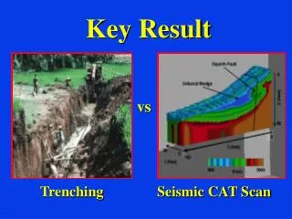
Introduction • Fractures • Fracture numerical models and the accurate seismic • responses are difficult to mathematically describe • Physical modeling can provide insight into seismic • responses caused by fractures • Seismic responses from fractures can be evaluated/ • interpreted using several established methodologies
Introduction • To look for lineaments or other anomalous patterns on • amplitude horizon slices. • Limitation – these anomalous patterns may not be in the • horizon plane • To pick seismic horizons and searching for changes of • formation time-thickness as a function of azimuth. • Limitation – results may suffer from interpreter picking errors • and or bias
Introduction • To evaluate subtle changes in amplitude with azimuth. • Limitation – much time and expertise is require for • accurate studies
Introduction Volumetric Attributes • Benefits: • Applied to uninterpreted data and to whole volume • Saves time from picking horizons • No unintentional interpreter errors and/or bias introduced
Introduction • Volumetric attributes types applied: • Amplitude • Coherence • Curvature
Introduction Amplitude • Color cube • Variable density • - Positive amplitude Coherence Energy Ratio
Introduction Curvature • Positive • Negative
Introduction Principle Component Filtering Def: a structure-oriented noise filter that retains coherent events; based on multi-window analysis of best-fit data to estimated dip/azimuth.
synform saddle bowl antiform dome Lineament Quantification s=-1.0 The shape index, s: Strike s=-0.5 s=0.0 Curvedness, c: Strike s=+0.5 s=+1.0 Principal curvatures (Bergbauer et al., 2003)
Methodology • Build Physical model with vertical fractures • Collect volume of data of various offsets over elastic physical model with embedded fracture media • Process 3D cubes and apply set of volumetric geometric attributes
Methodology • Evaluate fracture discrimination using volumetric attributes • Amplitude • Coherent energy ratio • Positive curvature • Negative curvature • Increase resolution using special filters • Principle component filter • Lineament filter Chopra & Marfurt, 2007
Physical Modeling Benefits of Physical Modeling • Experimental repeatability & controlled conditions • Very cost-effective compared to field work • Physics of elastic energy propagating through physical • models is same as real earth. • Arbitrary earthlike conditions closer to real earth data than • numerical modeling
Physical Modeling Some Limitations • Limited bandwidthStrong resonance at one frequency-- • Limited to materials with specific elastic parameters • Difficult to build lateral velocity variations • Labor intensive • Can not model all real earth materials/layers, e.g. • weathering layers
AGL’s 3m by 2m by 1.5m marine acquisition modeling system PhysMod - 17
Fracture Construction Glass slides x Glass blocks 1.1 cm Resin 35.5 cm Fracture model under construction showing glass slides in situ y
HTI model x Fracture zone y 50.8 cm 63.5 cm
Acquisition & Processing Geometry
Acquisition & Processing Geometry
1071 CDP 1360 2 2.5 3 Line 2151
Line 2140 500 m Offset 1071 CDP 1360 2.2 Time (s) 2.4 2.6 + -
Line 2140 500 m Offset CDP 1150 1202 Curvature 2.4 2.6
Positive amplitude 2.4 x y 500 m Offset z Time (sec) Line No 2144 2.5 1360 CDP No. 1071 -4000 Amplitude = 190.92 4000
Positive amplitude 500 m Offset 1100 CDP No. 1320 z 2040 x y Line No 2140 2.5 Time (sec) 2.4 -4000 Amplitude = 190.92 4000
CDP No 1080 1120 1160 1200 1240 1280 1320 1360 CDP No Time (s) Time (s) 2040 2060 2080 2100 2120 2140 Line No -100 -50 0 50 100 0 Coherence 1 Coherent/ Total Energy 1000 m 500 m offset, 2.356 sec
CDP No 1080 1120 1160 1200 1240 1280 1320 1360 - Coherence + Time (s) 2040 2060 2080 2100 2120 2140 Time (s) Line No -100 -50 0 50 100 Coherent/ Total Energy 1000 m 500 m offset, 2.494 sec
CDP No 1080 1120 1160 1200 1240 1280 1320 1360 Time (s) Line No (-) (+) 2040 2060 2080 2100 2120 2140 Most Positive Curvature 1000 m 500 m offset, 2.356 sec
CDP No 1080 1120 1160 1200 1240 1280 1320 1360 Time (s) Line No (-) (+) 2040 2060 2080 2100 2120 2140 Most Positive Curvature 500 m offset, 2.494 sec 1000 m
CDP No 1080 1120 1160 1200 1240 1280 1320 (-) (+) 2040 2060 2080 2100 2120 2140 Line No Time (s) Most Positive Curvature 1000 m 1000 m offset, 2.552 sec
500 m offset, 2.494 sec 1000 m offset, 2.552 sec
CDP No 1080 1120 1160 1200 1240 1280 1320 1360 (+) Time (s) Time (s) 2040 2060 2800 2100 2120 2140 Line No Time (s) (-) Most Negative Curvature 1000 m 500 m offset, 2.358 sec
CDP No 1080 1120 1160 1200 1240 1280 1320 1360 (+) Time (s) Time (s) 2040 2060 2800 2100 2120 2140 Line No Time (s) (-) Most Negative Curvature 1000 m 500 m offset, 2.494 sec
CDP No 1080 1120 1160 1200 1240 1280 1320 1360 (+) Time (s) 2040 2060 2800 2100 2120 2140 Time (s) Line No Time (s) (-) Most Negative Curvature 1000 m 1000 m offset, 2.552 sec
500 m offset, 2.494 sec 1000 m offset, 2.552 sec
(-) (+) (-) (+) Most Positive Curvature Most Negative Curvature 500 m offset, 2.494 sec
Special type of filtering to further isolate already detected fracture zone • Principle component filter • Lineament
SOF 500 m Offset Physical Modeling View 2 1071 1360 2.6 (-) Amplitude (+) Time z y x 2.4
SOF 500 m Offset Physical Modeling View 2 x y z 2.4 (-) Amplitude (+) Time 1360 2.6 1071
y Lineament 500 m Offset Physical Modeling x z -90 Azimuth=0 90 1100 1350
Display of structural lineaments Strike -90 0 +90 strong Lineament Intensity weak 2D color bar for lineament attribute (strike=azimuth of valley/ridge) (al-Dossary and Marfurt, 2006)
y x z Physical Modeling Lineament 500 m Offset 2.4 Time (s) -90 Azimuth=0 90 2.6 2140 2040 ALL OTHER COLORS MADE TRANSPARENT
Positive Amplitude Principle Comp Filter Most Positive Curvature Most Negative Curvature