L-Tracker Fitter Status
420 likes | 574 Vues
This outline details the progress and objectives of the L-Tracker project at UC Irvine, led by James L. Popp. The meeting focuses on developing pattern recognition algorithms to improve the tracking performance, discussing ongoing fixes in the existing code, and assessing the fitter's performance under ideal and finite resolution conditions. Key points include the identification of bugs, re-evaluation of code structure, the establishment of a longitudinal tracker geometry, and analysis of simulation results. The findings aim to enhance momentum determination and cluster recognition efficiency.

L-Tracker Fitter Status
E N D
Presentation Transcript
L-Tracker Fitter Status James L. Popp UC Irvine February 6, 2005 MECO Collaboration Meeting
Outline • Goal: Develop pattern recognition with the longitudinal tracker beginning with simulated raw detector signals (cluster formation, etc.) • Summarize what we have fixed and are fixing in the existing L-tracker pattern recognition and fitter code developed at UCI • Discuss maximum likelihood fitter performance under ideal conditions • What happens to fitter results when finite spatial resolution is added • Conclusions & Plans James L. Popp, UC Irvine L-Tracker Fitter Status
Code Repairs • Evident in early 2004: that the code we had was not performing as well as we expected with MECOtracker001.gmc • After many attempts to find a “quick fix” yielded little progress, we decided to break the code up into smaller parts and test each one. • Fitter & pattern recognition had • Numerous bugs • Designed too closely around a simplified detector • Geometry & absorber change • The size of the whole project required some coordinated division of labor: • Fitter (some issues remain) • “Helix” pattern recognition • Straw cluster recognition • Cluster reconstruction w/ realistic inefficiencies • etc. James L. Popp, UC Irvine L-Tracker Fitter Status
Physics Deadbeats in Pittsburgh • Cleaned up fitter, after some consultation with TJ • Next…results using ideal position information James L. Popp, UC Irvine L-Tracker Fitter Status
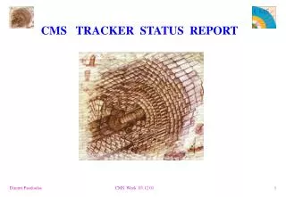
Longitudinal Tracker Geometry: “Octagon with eight vanes” – tilted modules Straws: 2.6 m length 5 mm diameter, 25 mm thickness – 2800 straws Three layers per plane, outer two resistive, inner conducting Pads: 30 cm 5 mm wide cathode strips affixed to outer straws Position Resolution: in-plane perp to wires 0.2 mm, along wires 1.5 mm James L. Popp, UC Irvine L-Tracker Fitter Status
L-Tracker Setup: Current Fitter Studies • GMC/crd/tracker/MECOtracker001.gmc • Fitter tries to determine the most probable momentum entering tracker • Requires at least 5 module crossings (redundancy) • Uses no more than 8 (could be more) James L. Popp, UC Irvine L-Tracker Fitter Status
Simulation & Reconstruction: ideal conditions • GEANT: Conversion in Al target • Cluster cuts: approx. 48% • Tracker: at least • 5 module crossings • 1 straw hit per crossing • Module crossing position • 1st module entry point (x,y,z) • Pitch angle cut: > 40 degrees • Input to fitter: momentum from simple helix fit to module crossings • Fitter cuts: approx. 35% • Likelihood function FWHM < 0.6 MeV • Max. scattering angle < 0.1 radians • Pitch angle: 45 – 60 degrees • Trigger energy deposition > 75 MeV James L. Popp, UC Irvine L-Tracker Fitter Status
Mu-e: Pitch Angle • Reconstructed entry angle • True entry angle James L. Popp, UC Irvine L-Tracker Fitter Status
Mu-e: Momentum • Reconstructed entry momentum • True entry momentum • Reconstructed minus true….next slide… James L. Popp, UC Irvine L-Tracker Fitter Status
Mu-e: Intrinsic Resolution • Mean (gaussian) = - 0.045 MeV/c • Standard deviation (gaussian) = 0.12 MeV/c James L. Popp, UC Irvine L-Tracker Fitter Status
Mu-e Resolution • Noise/Signal = 0.05 • Acceptance = 0.21 • Signal window minimum = 103.3 MeV James L. Popp, UC Irvine L-Tracker Fitter Status
Mu-e Conversion and DIO • Protons on production target: • Muon stopping efficiency: • Experiment run time: • Observation time window efficiency: 0.49 • MECO L-tracker acceptance: 0.21 • Assume • Probability for mu-e conversion: • Expected number of mu-e events: 6.1 • Table 5 – MECO memo 099: • Expected # DIO above 100 MeV = James L. Popp, UC Irvine L-Tracker Fitter Status
Mue and DIO Energy Spectra • DIO: 859,800 events • Energy: 100 – 105 MeV • Mu-e: 81,626 events • Normalization • values in previous slide James L. Popp, UC Irvine L-Tracker Fitter Status
In-plane z normal Finite Spatial Resolution • Gaussian random variables • In-plane direction (perp wires) • z direction (parallel wires) • Standard deviations • Add random numbers to true module crossing (entry) points Tracker module cartoon James L. Popp, UC Irvine L-Tracker Fitter Status
Mu-e: Pitch Angle & Momentum • Spatial resolution seems to have relatively small effect - deceptive • Leads to large scattering angle estimates when crossings are close together James L. Popp, UC Irvine L-Tracker Fitter Status
Mu-e: Intrinsic Resolution • Spatial resolution – Gaussian fit • Perfect: mean = - 0.045 MeV/c, Standard deviation = 0.119 MeV/c • Finite: mean = - 0.054 MeV/c, Standard deviation = 0.154 MeV/c James L. Popp, UC Irvine L-Tracker Fitter Status
Mu-e Resolution James L. Popp, UC Irvine L-Tracker Fitter Status
segments Spatial Resolution: Lever arm effect • Vertical axis: scattering angle (radians) • Horizontal axis: minimum of 2 adjacent segments sharing the angle (cm) James L. Popp, UC Irvine L-Tracker Fitter Status
Mu-e Likelihood Function: Spatial Resolution • Illustrate point further: • Left: No smearing • Right: Smearing – gaussians James L. Popp, UC Irvine L-Tracker Fitter Status
Conclusions & Plans • Likelihood function: modified to include effect of spatial resolution • Cluster recognition routines are under development • Cluster reconstruction is not far from completion • Incorporate cluster angle (local crossing angle) in likelihood function • Simulate pad & crystal signals… James L. Popp, UC Irvine L-Tracker Fitter Status
END James L. Popp, UC Irvine L-Tracker Fitter Status
Requirements – Resolution • The Tracker must provide precise momentum measurements to separate conversion signal events from muon decay in orbit (DIO) in a 1 T field. • The end point energy for DIO electrons coincides with the conversion signal, the end point spectrum falls as the 5th power of E, thus the level of DIO background in the signal region is sensitive to the resolution function; both the central (gaussian) region and high side tails • To obtain a signal / noise ratio of 20 for a nominal conversion signal of Rme = 10-16 requires an energy FWHM < 1 MeV The resolution is dominated by multiple scattering, thus material must be kept to a minimum Chamber r – f res. of 0.2 mm and z res. of 1.5 mm are adequate and achievable DIO Background convolved with detector response Acceptance wrt perfect detector for fixed 20:1 S/N GEANT conversion signal simulation James L. Popp, UC Irvine L-Tracker Fitter Status
Requirements – Rate Handling, Efficiency • A beam intensity of ~1011 stopped muons / sec implies that the detector must be capable of operating in a high rate environment. • This has driven the choice of 5 mm diameter straws and fast gas as the basic detector element. Note that the multiple scattering contribution to the resolution drives us to use thin walled (25 mm) straws • The majority of DIO electrons are at low pTrelative to signal events, thus the active elements of the detector are at large radius with respect to the stopping target • The detector must have reasonable efficiency to make the most of the sensitivity provided by the intense stopped muon beam. This drives a close packed straw array. • Reconstruction efficiency will be discussed in detail later in the talk James L. Popp, UC Irvine L-Tracker Fitter Status
Two Geometry Options • Two geometries under consideration (details follow) • “Longitudinal” (or simply “L”) Tracker with straws (nearly) parallel to the DS axis • “Transverse” (or “T”) Tracker with straws perpendicular to the DS axis • The nature of the event information and the engineering challenges associated with the construction are quite different for each arrangement • We have formed a “Tracking Chamber Advisory Committee” to evaluate both variants and recommend a choice to the MECO Executive Committee • We do not have an ETA on this decision yet, although (currently) this system is not on the MECO critical path James L. Popp, UC Irvine L-Tracker Fitter Status
Tracker Studies • Existing Efforts • L Tracker prototypes at Houston and Osaka using different straw types • Front-end electronics work at Houston that is largely applicable to either the L or T variants • Simulations of performance in the presence of backgrounds at UCI (L Tracker) and NYU (T Tracker) • New Initiatives this year • T Tracker mechanical design at Syracuse University • Additional front-end electronics at UVA, LBL • Simulation software coordination via Berkeley • Trigger/DAQ/Back-end electronics design at BU, UMass, NYU James L. Popp, UC Irvine L-Tracker Fitter Status
Tracker Simulations • Effects Modeled • GEANT3 detailed geometries including straw walls, wires, gas, manifolds • Noise hits fromg, p, n, at the nominal rate and doubled • Resolution – 200 mm per straw for T tracker 200 mm (r-j) 1.5 mm (z) per cluster for L tracker, both with tails out to 2.5 mm at 1% • Delta ray effects on rates • Energy loss (Landau fluctuations) and Molieré scattering in the stopping target • Beginning to work with GEANT4 as well • Remaining to be done • Hit digitization in the L Tracker, straws and pads • L Tracker cluster recognition • B field effects on drift performance • Support structures James L. Popp, UC Irvine L-Tracker Fitter Status
L Tracker Detector Rates vs. Time Rate [MHz] Rate [kHz] Full time between proton pulses Detection time interval 25 20 15 10 5 0 800 700 600 500 400 300 200 100 0 m-capture protons beam electrons m- decay in flight 0 400 800 1200 700 900 1100 1300 time with respect to proton pulse arrival time [ns] Very high rate from beam electrons at short times – potential problems with chamber operation Protons from m capture are very heavily ionizing – potential problems with noise, crosstalk Rates are similar (not identical) for T tracker, both highly dependent on radial position near inner edge James L. Popp, UC Irvine L-Tracker Fitter Status
Tracker Reconstruction • Codes for reconstructing events in each geometry have been developed independently at different institutions, often with different underlying assumptions • We have begun integrating the two approaches, we are still in the early stages. See Yury’s talk for more on this effort. • All current tracker reconstruction efforts have been based solely upon drift distance or straw positions. Additional information remains to be exploited: • Both trackers: • Pulse height to remove protons – for “free” via the use of the Elefant readout chip. • L tracker • Pulse-height for Compton electron rejection • Pulse-height for proton rejection, r-f and z hit correlation • Comparison of r-f and z hit timing to match hits in the two views – good to a few ns • Straw number correlation with z position for valid helices, i.e. order of r-f hits in each module is correlated with z position due to tilt and to lesser extent to energy loss • Use of local (cluster) track angle and timing information in pattern recognition to reduce combinatoric search (improves speed) • Some of these implemented in background rejection already (e.g. local track angle to reduce mis-reconstruction background) James L. Popp, UC Irvine L-Tracker Fitter Status
L Tracker Pattern Recognition & Fitting • Look for circles in r-f hits • Match with z hits – all combinations are tried • Hit positions are currently taken from detector crossing points, but these will ultimately be obtained via cluster finding • Following application of pre-selection cuts (following slide) raw helix info is passed to a maximum likelihood fitter. James L. Popp, UC Irvine L-Tracker Fitter Status
L Tracker Event Selection • The energy of the GEANT primary electron at the entrance of the electron calorimeter is at least 75 MeV. • The agreement of the projected entry position at the electron calorimeter for the fitted track is within 20 cm of that given by the GEANT primary electron. • The maximum scattering angle at each detector element < 0.1 rad • 45 º < pitch angle < 60º • The fitting uncertainty is less than 600 MeV. • The total number of clusters is at least 6 • There are no missing clusters on the track where it intercepts any detector element. James L. Popp, UC Irvine L-Tracker Fitter Status
Mis-reconstruction • Mis-reconstructed tracks like this one are potentially a source of background from very low energy DIO electrons that reconstruct many s above the actual energy • Difficult to study, since orders of magnitude more low energy electrons • Technique of increasing rates, then reducing observed background by weighting factor of (rT/rMC)n, where rT and rMC are the true and MC rates, and n is the number of noise signals used in the background event • One additional cut: event rejected if a lower momentum track is found real e- from - decay fake high p track James L. Popp, UC Irvine L-Tracker Fitter Status
L Tracker Resolution • 2 107 reconstructed conversion events • The intrinsic resolution is 180 keV James L. Popp, UC Irvine L-Tracker Fitter Status
L Tracker Signal vs. Background • DIO contribution is known spectrum convolved with “measured” signal resolution function • The acceptance is 19% for NBack / Nsignal = 0.05 • For B(m→e) =10-16 this amounts to 5 conversion events and 0.25 DIO background in the signal region James L. Popp, UC Irvine L-Tracker Fitter Status
Summary of L Tracker Results • Additional studies of straw material thickness, overall detector length, and minimum number of clusters on the candidate track James L. Popp, UC Irvine L-Tracker Fitter Status
T Tracker Resolution with Background • Nominal background and 25 µm • Delta-ray and straw inefficiency • Kalman filter reconstruction • Tracker Resolution = 0.19 MeV/c • Plot is the difference between reconstructed input momentum and actual input momentum Average straw rate 550 kHz Straw eff. Overall acceptance 100% 19.2 % 97% 18.7 % James L. Popp, UC Irvine L-Tracker Fitter Status
T Tracker DIO Reconstruction with Background • 1M DIO events (> 100 MeV/c) were generated 20 times more than expected Fit by Norm x (Emax - E)5 • 3 event found in search range > 103.5 MeV Background 3 / 20 = 0.2 event Muon Conversion Signal 5.5 events expected for Br = 10-16 Background/Signal Ratio = 0.03 (Same conditions) James L. Popp, UC Irvine L-Tracker Fitter Status
Summary of T Tracker Results • Results at nominal background rate without and with delta-ray and straw inefficiencies of 3% James L. Popp, UC Irvine L-Tracker Fitter Status
Proton Contribution to Tracker Rates Protons are very heavily ionizing – up to 50 times minimum ionizing Protons below ~18 MeV absorbed in target Rate hitting tracker reduced by absorbers – further optimization possible Studies of response of chambers to low energy protons planned at TUNL at Duke University 105 103 10 all generated protons 100 10 1 protons hitting tracker 0 20 40 60 80 100 Proton energy [MeV] James L. Popp, UC Irvine L-Tracker Fitter Status
Muon-electron conversion & DIO • Finite Spatial Resolution James L. Popp, UC Irvine L-Tracker Fitter Status
Mue and DIO: Finite Spatial Resolution • Yo mama James L. Popp, UC Irvine L-Tracker Fitter Status
New L-Tracker Design James L. Popp, UC Irvine L-Tracker Fitter Status