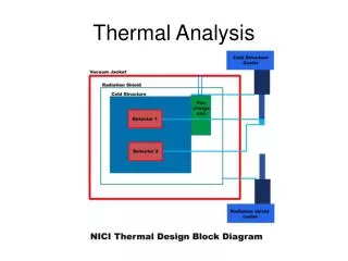
MICE project Thermal analysis
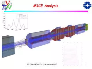
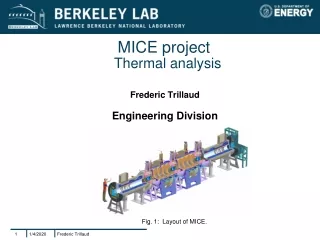
MICE project Thermal analysis. Frederic Trillaud Engineering Division. Fig. 1: Layout of MICE. Content. Introductory material: Description of the geometry. Cast3M (Finite Elements solver) and assumptions. Material properties. Cryocoolers characteristics.


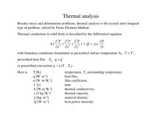
MICE project Thermal analysis
E N D
Presentation Transcript
Frederic Trillaud MICE projectThermal analysis Frederic Trillaud Engineering Division Fig. 1: Layout of MICE.
Frederic Trillaud Content • Introductory material: • Description of the geometry. • Cast3M (Finite Elements solver) and assumptions. • Material properties. • Cryocoolers characteristics. • Heat by radiation: super-insulation. • Steady state Analysis. • Recommendations • References.
Frederic Trillaud Description of the geometry Current leads (Red) Heat sinks (bleu) Copper plate (orange) Windings (Red) G10 rods (Green) towers (Dark grey) Insulation (Green) Thermal shield (grey) Helium vessel (Sky) Various tubes (blue) Supports (brown) G10 straps (Green) G10 insulation (green strip)
Frederic Trillaud Code 3D Finite Elements: Cast3M • Code CasT3M: non-linear model. Solver based on Theta-method solving the transient heat balance equation with the heat capacity set to zero. Convergence in 10 steps with a criterion equal to 1e-6, 534981 nodes. • Assumptions: • Perfect connections between parts. • Steady state. • Fixed temperature at the boundaries (300 K and 4.2 K) and fixed heat flux (current leads). • Normalized thermal conductivities and specific heat capacities for some geometries. • Material properties as a function of temperature (4 K to 300 K). • Normalized thermal conductivity and specific heat capacity taking into account the geometrical differences between the model and the actual geometry: • Thermal conductivity: • Specific heat capacity:
Frederic Trillaud Boundary conditions and geometrical details • Fixed temperatures at boundaries: tubes, G10 straps, supports, cryocoolers. • Geometrical limitations due to the complexity of some of the parts. The first principle is respected (Qsink = Qradiation + Qcond). However, the local thermal profile is expected to differ. G10 strap, boundary conditions Model of connection between one of the G10 strap and the thermal shield. Qcond Qsink System Qradiation
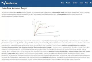
Frederic Trillaud Material properties • Fit equations are compared to data found in the litterature. • Overall agreement within 15 %. • Data sources: see the last slide (References).
Frederic Trillaud Implementation of super-insulation • The radiation heat load through super-insulation layers was simulated as a heat exchange coefficient (based on an equivalent thermal conductivity: 5e-5 W/m-K [See J.W. Ekin]): • The total thickness of the super-insulation, emli, is given by: • Where the number of layers, nlayers, is equal to 50. • The optimum thickness per number of layers given by J.W. Ekin (p. 38), npct, is equal to 30 layers per centimeter.
Frederic Trillaud Cryocoolers: operating points
Frederic Trillaud Current lead: copper and HTS (1/3) • Two questions are addressed: • Expected temperature profile in operation and fault mode. • Minimum heat load to be extracted at the connection between the copper and HTS lead. • The second question deals with the necessity to keep the HTS lead below the current-sharing temperature which depends on current and magnetic field. • In the subsequent analysis, the critical surface of the HTS lead is not taken into account.
Frederic Trillaud Copper and HTS leads (2/3) T1 Φ1 • Heat balance equation: • Analytical solution: • Flux conservation: • Maximum temperature (HTS): • Ratio length to cross-section area, l/A: l1 1 Copper Φ3 Φ2 l2 2 • Assumptions: • Adiabatic conditions. • Steady state. • Uniform cross-section area per section. • Clamped temperatures at boundaries. • Average thermal conductivity and resisitivity. • Quasi-static quench over the entire length of the HTS lead. HTS T2
Frederic Trillaud Copper and HTS leads (3/3) • Minimum extracted power to keep the connection below 70 K is equal to 7.8 W. • “Sensitivity” of the connection temperature during fault: 1.25 K/A • No matter how good is the connection: necessity of having voltage taps across the HTS leads It = 200 A 7.8 W
Frederic Trillaud Parameters: heat loads and boundary values • Heat sinks: • 3 pulsed tubes: • #1: 65 K • #2: 65 K • #3: 70 K • 1 Single stage cryocooler (not yet in use): 20 K (~50 W) • Here are the heat loads for the following simulations: • Conduction: • G10 straps: 300 K/4.2 K • End supports (Stainless steel and G10): 300 K • Current leads (It = 0 A): 4 W. • Radiation through super-insulation: • Source, enclosing vessel at 300 K: 9.8 W.
Frederic Trillaud Results: full solution on existing setup
Frederic Trillaud Thermal shield Al1100 • The question being addressed: • Do we need to replace the actual shield with a shield having a better thermal condutivity? • Fixed temperature at the cryocoolers: 65 K and 70 K (see next slide). • Despite a large difference in the thermal conductivity (factor superior to 2 at 100 K), the temperature diference is less than 4 K. • The actual thermal shield in the assumptions of the model should be adequate. Al6061-Ti
Frederic Trillaud Cryocooler towers Copper • The question being addressed: • Influence of the choice of material on the temperature drop across the towers? • Fixed temperatures at cryocoolers. • A material with a better thermal conductivity is beneficial. 70 K Heat sinks Al6061-Ti Al6061-Ti tubes 65 K 65 K Al1100F straps Al1100F
Frederic Trillaud Copper plate and fourth cryocooler (2/2) • The questions being addressed: • What is the heat load to match the temperature measured at the lead connection? • Will a fourth cryocooler help lowering the temperature profile at the lead connections? • The fourth cryocooler will defenitively help sinking a part of the power coming from the leads more over it will free cryocooler #3. #4 #3 #2 #1 3 cryocoolers 4 cryocoolers
Frederic Trillaud Fourth cryocooler copper connection Assumptions: -Steady state -The cryocooler takes full load assuming no other coolers (*). Φ • The question being addressed: • What is the expected temperature drop at the copper connection due to heat load? • Pure conduction: • Solution: • Fourth cryocooler characterisitic: T0 (*): beware, calculation not directly related to the previous slide.
Frederic Trillaud Recommendations • “Letting cost and time frame aside”. • Based on the previous analysis, the following items may be addressed: • Improvement of the connections between the copper plate and the thermal shield: material of better thermal conductivity, minimizing the distance, thicker walls. • A quality control may be imlemented to ensure proper welds between the various components critical to transfer heat from the shield to the cryocoolers: maximum contact areas, full solder penetration) • The current leads location may be better optimized to share the load over all the cryocoolers. • Appropriate location and number of thermal sensors and voltage taps must be further estimated: calibration of thermometry, defining salient parameters, ensuring that critical junctions and components are covered.
Frederic Trillaud References • WangNMR, Inc., “Final engineering design for MICE spectrometer solenoid magnets”, LBL P.O. 6806258. • Cast3M, http://www-cast3m.cea.fr/cast3m/index.jsp • J.W. Ekin, “Experimental Techniques for Low-Temperature measurements”, Oxford university press, 2006. ISBN: 0-19-857054-6 978-0-19-857054-7. • Y. Iwasa, “Case studies in superconducting magnets”, Springer, 2009. ISBN: 978-0-387-09799-2. • NIST database: http://cryogenics.nist.gov/ • E..D. Marquardt, J.P. Le,R. Radebaugh, “Cryogenic material properties Database”, 11th. International cryocooler conference, 2000. Source internet. • K.R. Hanby et al., “Handbook on materials for superconducting machinery”, NIST MCIC-HB-04, 1975. • Cryocomp software.
Frederic Trillaud References • G.E. Childs, L.J. Ericks, R. Powell, “Thermal conductivity of solids at room temperature and below”, NIST 1973. • J.G. Hust and A.B. Lankford, “Update of Thermal conductivity and electrical resisitivity of electrolytic iron, tungsten and stainless steel”, NIST publication 260-90, 1984. • N.J. Simon, E.S. Drexler, R.P. Reed, “Properties of Copper and Copper alloys at cryogenic temperatures”, NIST monograph 117, 1992. • V.J. Johnson, “A compendium of the properties of materials at low temperature (Phase I)”, Part 1, NIST WADD technical report 60-56 part II, 1961.