Download
1 / 26
400 likes | 745 Vues
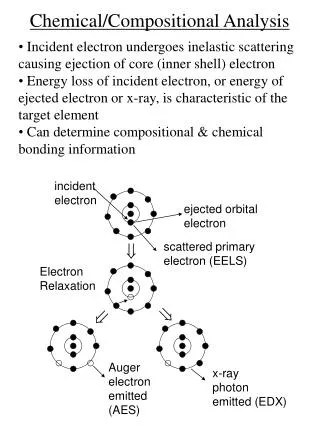
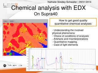
Nathalie Siredey-Schwaller | 09/01/2014. How to get good quality quantitative chemical analyses. Chemical analysis with EDX. Understanding the involved physical phenomena Choice of conditions of analyses Artefacts and misinterpretations Quantitative mapping Case of light elements.

E N D
Nathalie Siredey-Schwaller | 09/01/2014 How to get good quality quantitative chemical analyses Chemical analysis with EDX • Understanding the involved physical phenomena • Choice of conditions of analyses • Artefacts and misinterpretations • Quantitative mapping • Case of light elements On Supra40
Basic cares : sample preparation • Sample should be an electric conductor • Good electric conductivity of mounting • Good electric junction between sample and microscope : use of silver glue. Pay attention to the release of solvent. • Beware of oxyde layer at the surface of sample / cleanliness of the surface. • Surface of the sample : analysis depth is only a few microns • Surface should be out of contamination / clean • A precise quantification needs a flat and horizontal surface (phirhoZ method). • Measuring beam current : with a Cu tape put near the sample. This allows to measure the system factor. Sample spectra could then been compared to standards spectra.
Consequences of bad-electrical conductivity Deviation of beam Before recording spectrum After 5 min analysis Chemical signal changes Duane-Hunt limit should be identical to primary electron energy
Conditions for acquiring EDX signal Détecteur • Position of sample • No object between sample and detector • Infra-red camera is « off » : it induces noise signal Echantillons EDX detector WD = 8.5 to 9 mm, magnification > 300 Sample No analyses inside the hole Sas d’entrée
How to choose voltage and beam aperture ? • Voltage has to be chosen according to chemical elements expected Enough energy to eject an orbital electron of the element electron re-organization and emission of characteristic X-rays : K or L, (M) spectra The efficiency is the best for Eprimary beam = 2*Eionization • Analysis of light elements with small voltage (better signal/background ratio) • The highest-Z element to measure determines the voltage. • The voltage is more specially chosen according small content amount elements • Massic absorption coefficients for K spectra are the better known. • Usual values are15 keV, 20 keV • Beam current has to be chosen according to detector settings • Detector with high spectral resolution only accepts small intensity signal • Mapping needs good X-ray statistic per points, so high intensity signal
Measuring beam current / intensity of the signal • You have to do it in order to be able to compare your sample to standards. • Measuring System Factor SF • Conditions of measurments : on copper : • Focus to the good working distance • Tuning of the primary electronic beam : deviation (wooble), stigmatism. • Check the tilt angle (must be 0°and not 70°) • Choose the right device settings for the detector • Calibrate. Check if spectral position of Cu-Ka peak is OK. • Once this is done, nor the focus, nor the electron beam should be changed. Peak maxima match with color element lines
Choice of device settings • Detector has dead time, during which X-ray signal cannot be count. For good statistics, dead time shall not to exceed 10% • 60 kcps setting = better spectral resolution, higher dead time ( less acceptable intensity) • 275 kcps setting has less spectral resolution but accepts more signal. use of 60 kcps (40 keV) setting when peaks are close together, or overlap use 275 kcps (20 keV) when high statistic are needed (mapping) 60 kcps 275 kcps
Conditions of spectra acquisition • Analysed area should be homogeneous • What is a point spectrum ? • Existence of an emitting volume Theses phases cannot be analyzed separately
Size of analyzed particle is about 1 micron. At 25 kV, part of the Al matrix actually contributed to the signal.
Acquisition of a spectrum • Acquisition time : • higher is, better is signal / background ratio. X-ray emission is a statistic phenomenon : relative error is proportionnal to 1/√N.. Better is 106 counts. • Small as possible if existence of C-contamination of the sample or if sample is a bad electrical conductor. • When mapping, time spent on one point should be as less as possible use of high beam current • Identification of elements : • An element is identified by all characteristic X-rays. Color lines indicate the relative intensities. • All peaks should be explained • Beware of peaks overlapping • Beware of artefacts due to detector saturation : 2 photons E1, E2 are count together as one photon E=E1+E2. Exists in case of high signals.
Overlapping of peaks Surface C, O contamination peaks Double-photon peak
Quantitative analysis of a spectrum Two possible methods : • P/B ZAF method, without standards • Phirho(Z) method, with standards. Better in case of special conditions • Open library with the same device settings • Load the method of analysis • Quantify • Check quantitative analysis • Built spectrum should be identical to real spectrum • Total unnormalized massic sum should be equal to 100 % • Quite good quality analysis if result is between 96% and 104% • If result is less then 100% : maybe some elements have been forgotten
P/B ZAF method • ZAF : • Z = « atomic number » effect Ionization cross section, ability to stop the electrons according to the material. • A = absorption Depends on X-ray energy, density, depth of emission • F = fluorescence effect between elements One photon emitted by element A is absorbed by element B, inducing fluorescence. Photon from A is lost, one photon from B is observed. • Intensity of X-ray characteristics peaks is compared to intensity of background no standards are needed
F(rz) method • The function f(rZ) is calculated. This function describes emission of photons X, for a given material. It depends on : • Density r of the material • Depth Z, from where the emission occurs Z and A are simultaneously determined. It is then obtained curves, describing the emitted and emergent signals, according to the depth. • Fluorescence between elements is a phenomenon distinct from emission. Its calculation is similar to the previous case (P/B ZAF). • Analyze with standards : For each elemental X-ray characteristic peak, sample signal is compared to standard signal (known composition or pure standard). “k” is a corrective term from Z.A.F. corrections. “k” depends of amounts of all the elements existing in the sample and is only obtained after an iterative process.
Perfect match between real spectrum and built one Except for these energies (C contamination) Total sum is almost 100%
Choice of the method : triangle near « quantify ». • May be loaded from recorded files, may be created, may be saved.
The objects • One special point may be choose (beware of emitting volume !)
Lines may be analyzed • Acquisition : • Choose the number of points in the line. Distance between points should be higher than size of emitting volume. • Thanks to the global spectrum, determination of all the chemical elements. • Determination of the measuring time. According to the signal intensity. At least egal to number of points x 20 000 counts. • Possibility of increasing width of the line • Quantification : choose the appropriate method. • Saving : in the project or in a file .txt, readable by Excel. Indicates the intensity of signal = number of counts per second. Use this indication to determine the minimum analysis time on each point
The « hypermap » object • The aim is to record a mapping of a sample area. This mapping may be subsequently analyzed. • Acquiring a mapping : • Use of a high beam current in order to reduce analysis time. Consequently, use appropriate detector settings (130 kcps, 275 kcps) • Determination of the total points number • Determination of the total analysis time= nber of points * 20 000 counts • Select the chemical elements to display. • To begin, click on « Acquire » (parameters = right-hand triangle). To stop, click on the same button. The mapping is realized with a lot of quick scanning. This allows to reduce C contamination, charge effect. The mapping becomes more and more precise with time: signal / background ratio increases. • Save the mapping : in a separate file : .rtb or .bcf, usually quite big . In this file are recorded the full spectra of each point. • Quantitative analysis of mapping : Qmap • May be time-consuming, so to be done as a post-process. • Select the quantification method (triangle near « Qmap »). • To begin : click on « Qmap ». • Results may be displayed on maps, false color maps, or recorded on “.txt” files (1 for each elements) readable by Excel
Qualitative mappingbefore quantitative analysis • This mappingwasrealized on Ka-Si peakenergy • This isnot a Si-content mapping: atthisenergy, someotherspeaksoverlap • Alsobeware, in qualitative mapping, of variation in background signal • A quantitative mappingismandatory
N1 = Number of counts / second N2 = Number of points / line Minimum = 100 points S = Size of the image = HxV N2 = should be chosen to be H / d d = distance between two points (1,2 or 3 microns). N3 = (H/d) x (V/d) is the total number of points in the mapping Time of the mapping, for 20 000 counts per points is (in seconds) : N3 x 20 000 / N1
Chemical analysis including one light element • Preliminary considerations : Detector should have a good spectral resolution Characteristics X-rays of light elements have small energy. In this range, there is C contamination, usually of high number of X-ray characteristics peaks, bad transmission of the detector window. In order to increase signal/background ratio, primary electron energy should be small, which is usually incompatible with the other chemical elements • The best method is to measure out by difference, once all other chemical elements have been analyzed. This needs a careful analyzing of the other elements • PhirhoZ method with standards • Very good standards (at least 1 million counts standards) • Very good statistics of the spectrum (at least 1 million counts standards) • Check on an area not containing light element that total unnormalized sum is 100±1 %. Select « measure out by difference » inside the method
Thankyou for your attention