Shear Wall Structures
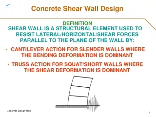
CE 636 - Design of Multi-Story Structures T. B. Quimby UAA School of Engineering. Shear Wall Structures. Shear Walls. Behave as tall cantilever beams. Deflection is predominately in flexure.

Shear Wall Structures
E N D
Presentation Transcript
CE 636 - Design of Multi-Story Structures T. B. Quimby UAA School of Engineering Shear Wall Structures
Shear Walls • Behave as tall cantilever beams. • Deflection is predominately in flexure. • The wall elements have high shear stiffness, mainly because the “beam” element has a depth that is large compared to it's span (level to level). • Economical for buildings up to 35 stories. • The walls can also be used to resist gravity forces.
Proportionate vs. Nonproportionate • Proportionate: • Walls, at each level, maintain their relative rigidities through out the height • There is no redistribution of overturning moments or shears at any level. • Nonproportionate: • The relative rigidities of the walls changes from level to level. • There is a redistribution of overturning moments and shears at one or more levels.
Proportionate Systems • All walls deflect the same when there is no twist. • Twisting takes place about the center of rigidity • Each wall on a given floor takes the Story Shear in proportion to their relative rigidities. • The author uses the bending stiffness of each pier to determine the relative stiffness (see section 9.2 of the text). • Our text considers walls to be without openings, which is generally true for tall buildings, but not necessarily so for short buildings. Openings in walls must be considered when computing relative stiffness.
Rigidity Calculations • “Reinforced Masonry Engineering Handbook” (by James Amrhein, published by the Masonry Institute of America) has an excellent treatment of shear wall analysis for low rise buildings. • Piers are viewed as being fixed against rotation at both ends (fixed-fixed) or at one end only (cantilevered, fixed-pinned). • Stiffness = 1/(deflection resulting from a unit load) • Amrhein'sequations for deflection consider both flexural and shear deflections.
Stiffness of a Solid Wall • Author's equation only considers flexural contribution to stiffness and considers only cantilever beam action, OK for tall buildings that have shear walls w/o openings. • See Amrhein's book, Table T-1i, for stiffness calculation including shear deformation effects and for different end fixity conditions.
Stiffness of a Wall with Openings • Need to determine the deflection of the wall under a unit load, then invert it. • Divide wall into individual piers and add up deflections.
Wall Stiffness Computation • Subdivide into piers • Find deflection of each vertical subdivision and add together • All piers in a given vertical subdivision must deflect the same. • The stiffness of a vertical subdivision is the sum of the stiffnesses of the individual piers. • Deflection = 1/stiffness
Example: Divide into Piers • Create five piers
Find Stiffness of each Pier • Use Amrhein's formulas for Fixed-Fixed piers. • The stiffness is the force that will cause a unit deflection in the pier.
Lateral Distribution: Flexible Diaphragms • Flexible diaphragms cannot transfer moment. • Flexible diaphragms are considered to act as simply supported beams between shear wall support. • Normally wood or steel decking w/o concrete. • Loads are distributed to walls according to tributary loads.
Lateral Distribution:Rigid Diaphragms • Story shear and Story Moment is distributed to each wall according to relative stiffnesses. • Determine location of center of rigidity and center of force to determine any eccentricity. • Story moment equals the story shear times the distance between the centers of force and rigidity.
NonProportionate Systems • Best solved by appropriate computer modeling. • The author presents a method similar to moment distribution to deal with nonproportionatenontwisting structures. We will not cover it. • If twisting is a factor, then the problem is too complex for hand solutions.
Important things to understand about nonproportionate behavior • There is redistribution of moments and shears at levels where changes occur. • Levels adjacent to change levels also participate in the redistribution. • Take some time to model a disproportionate system or two and explore the effects on shear and moment distributions.