Experiment 9
Experiment 9. Part A: Simulation of a Transformer Part B: Making an Inductor Part C: Measurement of Inductance Part D: Making a Transformer. Inductors & Transformers. How do transformers work? How to make an inductor? How to measure inductance? How to make a transformer?. ?.

Experiment 9
E N D
Presentation Transcript
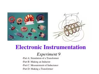
Experiment 9 Part A: Simulation of a Transformer Part B: Making an Inductor Part C: Measurement of Inductance Part D: Making a Transformer
Inductors & Transformers • How do transformers work? • How to make an inductor? • How to measure inductance? • How to make a transformer? ? Electronic Instrumentation
Some Interesting Inductors • Induction Heating Electronic Instrumentation
Some Interesting Inductors • Induction Heating in Aerospace Electronic Instrumentation
Some Interesting Inductors • Induction Forming Electronic Instrumentation
Primary Coil Secondary Coil Some Interesting Inductors • Coin Flipper Electronic Instrumentation
Some Interesting Inductors • GE Genura Light Electronic Instrumentation
Some Interesting Transformers • A huge range in sizes Electronic Instrumentation
Wall Warts Electronic Instrumentation
Some Interesting Transformers • High Temperature Superconducting Transformer Electronic Instrumentation
Household Power • 7200V transformed to 240V for household use Electronic Instrumentation
Inductors-Review • General form of I-V relationship • For steady-state sine wave excitation Electronic Instrumentation
Inductors-Review • Simple R-L Filter • High Pass Filter • Corner Frequency Electronic Instrumentation
Inductors-Review Electronic Instrumentation
Making an Inductor • For a simple cylindrical inductor (called a solenoid), we wind N turns of wire around a cylindrical form. The inductance is ideally given by where this expression only holds when the length d is very much greater than the diameter 2rc Electronic Instrumentation
Making an Inductor • Note that the constant o = 4 x 10⁻⁷ H/m is required to have inductance in Henries (named after Joseph Henry of Albany) • For magnetic materials, we use instead, which can typically be 105 times larger for materials like iron • is called the permeability Electronic Instrumentation
Some Typical Permeabilities • Air 1.257x10⁻⁶ H/m • Ferrite U M33 9.42x10⁻⁴ H/m • Nickel 7.54x10⁻⁴ H/m • Iron 6.28x10⁻³ H/m • Ferrite T38 1.26x10⁻² H/m • Silicon GO steel 5.03x10⁻² H/m • supermalloy 1.26 H/m Electronic Instrumentation
Making an Inductor • If the coil length is much small than the diameter (rwis the wire radius) Such a coil is used in the metal detector at the right Electronic Instrumentation
Making an Inductor • All wires have some finite resistance. Much of the time, this resistance is negligible when compared with other circuit components. • Resistance of a wire is given by l is the wire length A is the wire cross sectional area (prw2) s is the wire conductivity Electronic Instrumentation
Some Typical Conductivities • Silver 6.17x10⁷ Siemens/m • Copper 5.8x10⁷ S/m • Aluminum 3.72x10⁷ S/m • Iron 1x10⁷ S/m • Sea Water 5 S/m • Fresh Water 25x10-6 S/m • Teflon 1x10-20 S/m Electronic Instrumentation
Wire Resistance • Using the Megaconverter at http://www.megaconverter.com/Mega2/ (see course website) Electronic Instrumentation
Transformers • Note that for a transformer, the symbol shows two inductors. One is the primary (source end) and one is the secondary (load end): LS& LL • The inductors work as expected, but they also couple to one another through their mutual inductance: M2=k2 LS LL Symbol for transformer Electronic Instrumentation
Transformers IS IL Note Current Direction • Let the current through the primary be • Let the current through the secondary be • The voltage across the primary inductor is • The voltage across the secondary inductor is Electronic Instrumentation
Transformers • Sum of primary voltages must equal the source • Sum of secondary voltages must equal zero Electronic Instrumentation
Transformers • Note the following simplifying information for cylindrical or toroidal inductors • For Electronic Instrumentation
Transformers • Cylinders (solenoids) • Toroids Electronic Instrumentation
Transformers • Transformers are designed so that the inductive impedances are much larger than any resistance in the circuit. Then, from the second loop equation Electronic Instrumentation
Transformers • The voltages across the primary and secondary terminals of the transformer are related by Note that the coil with more turns has the larger voltage Electronic Instrumentation
Transformers • The input impedance of the primary winding reflects the load impedance. It can be determined from the loop equations Electronic Instrumentation
Transformer Rectifier • Adding a full wave rectifier to the transformer makes a low voltage DC power supply, like the wall warts used on most of the electronics we buy these days. Electronic Instrumentation
Transformer Rectifier Filtered Unfiltered Electronic Instrumentation
Determining Inductance • Calculate it from dimensions and material properties • Measure using commercial bridge (expensive device) • Infer inductance from response of a circuit. This latter approach is the cheapest and usually the simplest to apply. Most of the time, we can determine circuit parameters from circuit performance. Electronic Instrumentation
Determining Inductance • For this circuit, a resonance should occur for the parallel combination of the unknown inductor and the known capacitor. If we find this frequency, we can find the inductance. Electronic Instrumentation
Determining Inductance • Reminder—The parallel combination of L and C goes to infinity at resonance. Electronic Instrumentation
Even 1 ohm of resistance in the coil can spoil this response somewhat Electronic Instrumentation
Project 3: Beakman’s Motor • The coil in this motor can be characterized in the same way Electronic Instrumentation
Optional Project: Paperclip Launcher • A small disposable flash camera can be used to build a magnetic paperclip launcher Electronic Instrumentation