Download
1 / 42
461 likes | 834 Vues
Nanoscale Photovoltaics . Aldo Di Carlo. Dipartimento di Ingegneria Elettronica Università di Roma “Tor Vergata” aldo.dicarlo@uniroma2.it. PHOTOVOLTAIC CELL. Example of photovoltaic systems. Componenti di un sistema fotovoltaico. Module. Cell. Array.

E N D
Nanoscale Photovoltaics Aldo Di Carlo Dipartimento di Ingegneria Elettronica Università di Roma “Tor Vergata” aldo.dicarlo@uniroma2.it
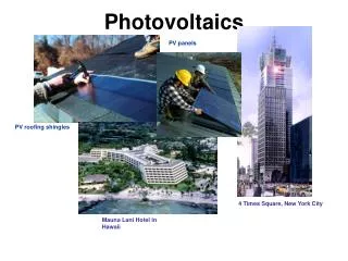
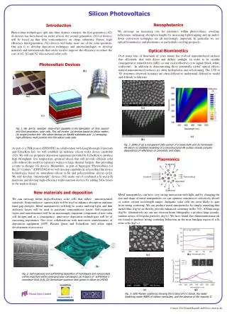
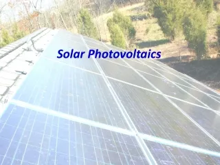
PHOTOVOLTAIC CELL Example of photovoltaic systems
Componenti di un sistema fotovoltaico Module Cell Array The photovoltaic system is made of an array of photovoltaic modules with additional electronics like charge controllers, inverters etc.
ContinuousCurrent Photovoltaic cell: working principle N-type silicon P-type silicon “Conventional” photovoltaic cells are based p-n junction between semiconductors.
Photovoltaic cell: short history 1941 Russell Ohl (Bell Labs) discover the silicon p-n junction and the effect of light on the junction 1954 Bell Labs researchers Pearson, Chapin, e Fuller demonstrated the photovoltaic cell with 4.5% efficiency
Solar Spectrum Spectral power density [(W/m2)/nm] Wavelength [nm]
Efficiency One of the most important parameters of the photovoltaic cell is the efficiency defined as: Max electrical power produced by the cell EFFICIENCY = h = Total solar power impinging on the cell Example: 10 W/dm2 h = 10% 1 W 1dm h = 20% 2 W 1dm It is important to increase as much as possbilethe efficiency.
Figures of merit Important features of the I-V curves · The intersection of the curve with the y-axis (current) is referred to as the short circuit currentISC. ISCis the maximum current the solar cell can put out under a given illumination power without an external voltage source connected. · The intersection with the x-axis (voltage) is called the open circuit voltage (VOC). VOCis the maximum voltage a solar cell can put out. · IMPand VMPare the current and voltage at the point of maximum power output of the solar cell. IMPand VMPcan be determined by calculating the power output Pof the solar cell (P=I*V) at each point between ISCand VOCand finding the maximum of P. Fill form factor The overall efficiency of a solar cell is larger for larger FF
Figures of merit PHOTORESPONSIVITY The photoresponsivity is defined as the photocurrent extracted from the solar cell divided by the incident power of the light at a certain wavelength. EXTERNAL QUANTUM EFFICIENCY The external quantum efficiency is defined as the number of charges Neextracted at the electrodes divided by the number of photons Nphof a certain wavelength incident on the solar cell POWER CONVERSION EFFICIENCY The power conversion efficiency is defined as the ratio of the electric power output of the cell at the maximum power point to the incident optical power.
Which are the factors influencing the cell efficiency ? EFFICIENCY MATERIALS TECHNOLOGY Single junctions Multiple junctions …. …. Silicon GaAs CdTe ….. …..
Bulk semiconductors Silicon Single crystal Multi crystalline Gallium arsemide (GaAs) Other III-V semiconductors Materials for photovoltaic cells CdTe Thin Films semiconductors • Amorphous silicon (a-Si) • Cadmium telluride (CdTe) • Copper-Indium diselenide (CuInSe2, o CIS) • Coper-Gallium-Indium diselenide (CIGS) Organic and hybrid materials - Small molecules - Polymers- Dye Sensitized Solal Cell
Beyond the Shockley-Queisser limit • The maximum thermodynamic efficiency for the conversion of unconcentrated solar irradiance into electrical free energy in the radiative limit, assuming detailed balance, a single threshold absorber, and thermal equilibrium between electrons and phonons, was calculated by Shockley and Queisser in 1961to be about 31%. • W. Shockley and H. J. Queisser. J. Appl. Phys. 32 (1961) 510. What do we do to achieve efficiencies > 31 % ? • Concentration • Multijunction • No thermal equilibrium Nanotecnology
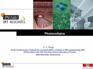
Andamento dell’efficienza delle celle fotovoltaiche Max lab efficiency on small size solar cells 40 36 Record ~40% Multijunctions (GaAs ed altri) 32 28 Monocristalline Silicon 24 Multicristalline silicon 20 EFFICIENCY (%) 16 12 CdTe 8 Organic: DSSC CIS e CIGS 4 Organic: polimer a-Silicon 0 1975 1980 1985 1990 1995 2000 2005 YEAR
Eg=1.9eV Eg=1.42eV Cell 1 Eg1 Eg=0.7eV Cella 2 Eg2<Eg1 Cella 3 Eg3<Eg2 Multijunctions
TCO p TCO aSi p i n i n 1 mm MultiJunction a-Si solar Cells Amorphous silicon absorption coefficient is larger than Silicon. We can then use thin layers of a-Si (few microns). Multijunctions solar cells
Photovoltaic generations First generation refers to high quality and hence low defect single crystal photovoltaic devices these have high efficiencies and are approaching the limiting efficiencies for single band gap devices Second generation technology involves low cost and low energy intensity growth techniques such as vapour deposition and electroplating Third generation multiple energy threshold devices; modification of the incident spectrum; and use of excess thermal generation to enhance voltages or carrier collection.
What about nanobjects ? Nanobjects can be use to avoid silicon in II generation photovoltaics and reduce the cost of the cell Nanobjects play a fundamental role to develop III generation photovoltaics
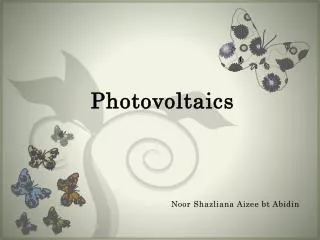
Structure of Dye Sensitized Solar Cells Glass Substrate Transparent Conducting Oxide (ITO or SnO2:F) Catalyst (Platinum, graphite) Electrolyte I-/I-3 Dye Molecules on TiO2 nanocristalline TiO2 Transparent Conducting Oxide (ITO or SnO2:F) Glass Substrate Why DSSC Nanocrystalline TiO2 Meas. Setup: Indoor Stability: Indoor Hematine Structure of DSSC Assembling DSSC Meas. Setup: Outdoor Stability: Outdoor Principle of DSSC Final Assembling of DSSC Process Repeatability Enocyanine (E163)
Monocrystaline Nanostructured Strong increase of optical density of the nanoporous film with respect to the monocrystalline film Very large effective area available for dye-TiO2 interaction The “nano” object: Nanocristalline TiO2 E (V) S* E [LUMO (S*)] – EC[TiO2] > E exciton binding energy -0.5 0.0 Exciton 0.5 So/S+ TiO2 Dye
Principle of Dye Sensitized Solar Cells No permanent chemical transformation in the materials composing the cell TCO TiO2 Dye Electrolyte Cathode Injection S* (LUMO) Fermi Level in TiO2 -0.5 E (V) V Max hυ 0.0 3I- I-3 Ox 0.5 So/S+ (HOMO) Load
Competition Dynamic in DSSC (source: O’Regan)
Dyes (1) • The optoelectronic properties (especially the absorption spectrum) can be tuned through the chemical design of novel dyes, even multicolored • Efficiencies: max 10 - 11% (in labs) • Lifetimes: few years Nikkei
Dyes (2) Synthetic Dyes Dyes synthesized with organic chemistry that have high absorption coefficients in the visible region. These dye can be dissolved in organic solvents. The optimal dye will absorb the broadest range of sunlight spectrum The molecule on the left: cis-bis(isothiocyanato)bis(2,2-bipyridyl-4-carboxilicacid-4-tetrabutylammonium carboxilate)ruthenium(II) Biological Dyes: Anthocyanins are found in red wines, blackberry etc. An anthocyanin has a carbohydrate (sugar, usually glucose) esterified at the 3 position. An anthocyanidin, termed the aglycone, does not have a sugar at the 3 position. Naturally occurring pigments from grapes always have a sugar bonded at the 3 position, though other compounds such as hydroxycinnamates and acetate may be involved. The presence of this sugar helps the anthocyanin maintain solubility in water. Efficiencies are about an order of magnitude lower than with synthetic dyes.
Conventional Cell Production Sistema di ricerca per la produzione di celle CIS Fornace industriale per la produzione di lingotti di silicio Apparato industriale per la diffusione Apparati per la fabricazione di celle al silicio amorfo (Uni. Toledo) • PECVD, hot-wire, sputtering • 13.56 MHz excitation • Gas handling for SiH4, CH4, PH3, B2H6, NH3 • Gas scrubber with toxic gas monitoring
DSSC Fabrication: “cooking recepies” MOVIE: downloadable from http://www.freenergy.uniroma2.it
How to create a DSSC 1-2) Put TiO2 on ITO and oven it @ 450 oC (Sintering) 3) Sinterizer Impregnation (immerge the cell in the blackberries!)
How to create a DSSC 4) Platinum on the counter electrode 5) Assemble the two pieces (25-50 mm distance) 6) Fill with electrolyte KI/I2 7) Seal the solar cell
Photovoltaic performance Absorption Spectra • QE 70-80% • Jsc = 15-20 mA cm-2 • Voc = 0.8 V • = 5-10% Voltage Source: J. Nelson • Challenges: • Improving photocurrent: dyes, light management • Improving photovoltage : minimise recombination alternative materials
Organic Photovoltaics DSSC Façade System at the CSIRO Energy Centre Newcastle, Australia CELLA FLESSIBILE SU PET KONARKA
DSSC • Inorganic Materials • Concerns: • Use of toxic metals like Cadmium • Use of toxic gasses in the manufacturing of PV, silane, hydrogen selenide • Can the materials be recycled or are they destined for landfills
Other approaches to exceed the Shockley-Queisser limit include hot carrier solar cells [1-3], solar cells producing multiple electron-hole pairs per photon through impact ionization [4,5], multiband and impurity solar cells [6,7], thermophotovoltaic/thermophotonic cells [6]. Photovoltaic with nanobjects • A. J. Nozik. Annu. Rev. Phys. Chem. 52 (2001) 193. • R. T. Ross and A. J. Nozik. J. Appl. Phys. 53 (1982) 3813. • D. S. Boudreaux, F. Williams, and A. J. Nozik. J. Appl. Phys. 51 (1980) 2158. • P. T. Landsberg, H. Nussbaumer, and G. Willeke. J. Appl. Phys. 74 (1993) 1451. • S. Kolodinski, J. H. Werner, T. Wittchen, and H. J. Queisser. Appl. Phys. Lett. 63 (1993) 2405. • M. A. Green. Third Generation Photovoltaics. (Bridge Printery, Sydney) 2001.
Enhanced photovoltage Carriers need to be extracted from the photoconverter before they cool. The rates of photogenerated carrier separation, transport, and interfacial transfer across the semiconductor interface must all be fast compared to the rate of carrier cooling. Enhanced photocurrent. Energetic hot carriers to produce a second (or more) electron-hole pair through impact ionization —a process that is the inverse of an Auger process whereby two electron-hole pairs recombine to produce a single highly energetic electron-hole pair. The rate of impact ionization is greater than the rate of carrier cooling and forward Auger processes. Nanobjects for very high efficiency !!! There are two fundamental ways to utilize the hot carriers for enhancing the efficiency of photon conversion. ISC VOC contact contact gap semiconductor ISC contact VOC contact gap In recent years, it has been proposed, and experimentally verified in some cases, that the relaxation dynamics of photogenerated carriers may be markedly affected by quantization effects in the semiconductor (i.e., in semiconductor quantum wells, quantum wires, quantum dots, superlattices, and nanostructures). Specifically, the hot carrier cooling rates may be dramatically reduced, and the rate of impact ionization could become competitive with the rate of carrier cooling
20 x 20 x 20 EU rule By 2020 EU should reduce by 20% the CO2 emission and increase the 20% renewable energies This means $$ for research in this field Modern Physics and Nanotechnology should now (re)consider the photovoltaic problem with new innovative solutions. There is a plenty of space for basic and advanced research Fundings and perspectives