Download
1 / 15
150 likes | 170 Vues
This proposal outlines the requirements for a picosecond resolution measurement detector in a synchronous detector setup, using CDF as an example. The detector has a cylinder shape, 1.5 meters radius, and 3 meters long, with individual tiles of 5 inches square. The design includes input/output bus lines, modules per line, event collision rates, and data generation details. It involves using MCPT anode aperture array, collector board overlay, simulation, assembly plans, and technology considerations like using IBM SIGE processes. Tools like Cadence and Mentor Graphics, IBM design kit, and contract with MOSIS will be utilized. The tasks include designing chips, simulations, board assembly, test facility setup, data acquisition, and testing of sample chips.

E N D
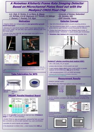
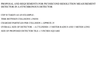
PROPOSAL AND REQUIEMENTS FOR PICOSECOND RESOLUTION MEASUREMENT DETECTOR IN A SYNCHRONOUS DETECTOR CDF IS TAKEN AS AN EXAMPLE : TIME BETWEEN COLLISONS =396NS CHARGED PARTICLES PER COLLISION = APPROX 25 OVERALL SIZE OF DETECTOR ---A CYLINDER 1.5 METER RADIUS AND 3 METER LONG SIZE OF PROPOSED DETECTOR TILE = 5 INCHES SQUARE
We require one set of input / output bus lines per 5cm of circumference which results in 189 lines for a 1.5 meter radius cylinder. The cylinder is 3 meters long which means we will have 60 modules per line. Each module covers 5cm square. The total number of 4 cell modules is then 11,340. There will be about 1 event every five collisions in each line of modules assuming 40 charge particles collision Data generated for each cell per event is about 5 bytes .
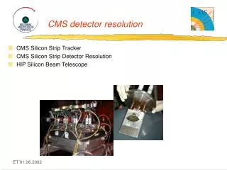
MCPT ANODE 1024 APERTURE ARRAY SHOWN
HSPICE SIMULATION OF 100 INPUT CELL ARRAY 1 OUTPUT 30ns WINDOW
TYCO ELECTRONICS ELASTOMETER TECHNOLOGY Since the MCPT is sealed with indium solder we cannot use regular lead tin solder to connect with an external circuit board. We are planning to use either a conductive epoxy or an elastometer layer to sandwich the circuit board to the tube. The substance below is a layer of silicone with conductive wire arrayed and embedded in the silicone insulator
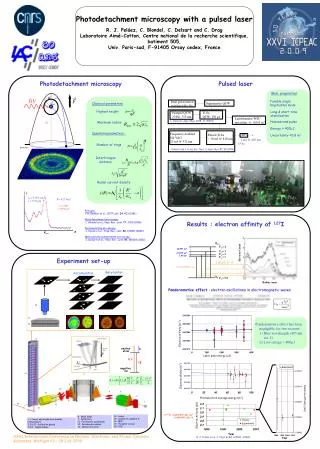
WHY SIGE PROCESS? PUBLISHED PAPERS FROM AN IBM DESIGN GROUP ON USING EARLIER VERSIONS OF THIS PROCESS (5HP) REPORTING PLL OSCILLATORS WITH SUB PICO SECOND JITTER (IBM J RES&DEV VOL 47 NO2/3 MARCH/MAY 2003 SiGe BiCMOS INTEGRATED CICUITS FOR HIGH-SPEED SERIAL COMMUNICATIN LINKS)
OUR TOOLS, PLANS AND PROBLEMS TOOLS INCLUDE CADENCE AND MENTOR GRAPHICS DESIGN TOOLS, IBM DESIGN KIT FOR SiGe PROCESS. HELP FILES FROM IBM, CONTRACT WITH MOSIS TO ENABLE FABRICATION. WHAT WE MUST DO. WE NEED 2 DIFFERENT CHIPS DESIGN CHIPS SIMULATE DESIGN DESIGN BOARD ASSEMBLE A SUITABLE TEST FACILITY DESIGN DATA ACQUISTION FOR TESTING BUY CHIP SAMPLE LOT (EXPENSIVE $70K) TEST CHIPS