Download
1 / 54
560 likes | 886 Vues
Water Flow in Glaciers. 1. Introduction 2. Water sources 3. Water flow (a) permeability (b) hydraulic potential (c) pressure and conduit size (d) direction of flow (e) unsteady state conditions 4. Storage 5. Subglacial drainage systems (a) Discrete systems

E N D
Water Flow in Glaciers 1. Introduction 2. Water sources 3. Water flow (a) permeability (b) hydraulic potential (c) pressure and conduit size (d) direction of flow (e) unsteady state conditions 4. Storage 5. Subglacial drainage systems (a) Discrete systems (b) Distributed systems
References Bennett, M.R. and Glasser, N.F. (1996) Glacial geology: ice sheets and landforms. Wiley, Chichester. Chapter 4 Glacial meltwater
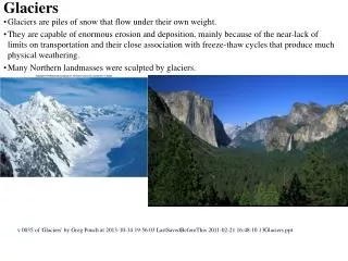
Introduction What is the impact of water in glaciers? • In mass balance • Sliding • Subglacial sediment deformation • Hydrological systems • Sediment transport
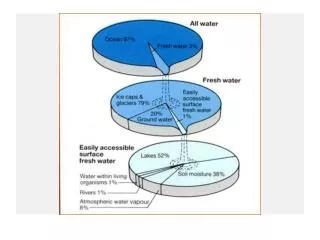
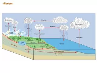
Water sources Sources • ice melt • snow melt • rainfall • runoff from ice-free slopes • release of stored water
Surface melting • temperature • radiation flux • highly variable in time and space Rainfall • rain on snow events • greater runoff generation • highly variable in time and space Englacial and subglacial melt • friction from ice deformation (sliding) • more constant in time?
Water flow Permeability • primary permeability • secondary permeability
Primary permeability • intact ice and snow • high for snow and firn - linked pore spaces • very low for ice • ice at pmp interconnected veins and lenses between ice crystals Secondary permeability • tunnels and passage ways (mm - m's) • most water draining through glaciers
Hydraulic potential Available energy at a particular time and place • Surface streams - potential depends on elevation • At base - depends on elevation and pressure In an englacial or subglacial stream: f = f0 + fe + Pw • where • Ø = hydraulic potential • Ø0 = a constant (conduit size & shape) • Øe = elevation potential • Pw = water pressure
The elevation potential is the product of the weight of water and it elevation: fe = rw.g.z where w = water density g = gravitational acceleration z = elevation
In natural conditions water pressure can vary between: • atmospheric • cryostatic Cryostatic pressure is the product of the weight and thickness of the ice: Pi = ri.g.(H-z) where Pi = ice pressure i = ice density H = altitude of the ice surface z = elevation at site
Vadose zone • connected with the atmosphere • at atmospheric pressure • potential depends on elevation Phreatic zone • saturated • no air in conduits • above atmospheric pressure
Effective pressure N = Pi - Pw When Pw is zero the effective pressure is the cryostatic pressure Controls • glacier motion • bed deformation
If Pw = Pi (ie N=0) • the water can support the whole weight of the glacier • the water can lift the glacier off its bed Local scale • where cryostatic pressures are lower than normal • eg downstream side of protuberances Large scale • subglacial lakes
Pressure and conduit size Pressure in water filled conduits controlled by: Frictional heat • melt and passage enlargement Ice deformation • pressure gradient between the ice and water • tendency to decrease passage size
Equilibrium conditions Pw = Pi + Pm where Pm = pressure change to melting or contraction
Negative Pm • pressure drop due to efficient melting • melt rates increase with increasing passage radius • Larger channels • carry more water • dissipate more heat to the area of their walls Positive N (N = Pi – Pw ) • ice deformation rates increase • large pressure differences between the water conduit and ice lead to rapid closure
Two important implications: 1. Melting and deformation allow conduit expansion and contraction in response to Pw increases and decreases If Pw increases N falls, reducing conduit closure rates • Þ passages can only become larger through melting If Pw falls, the increased pressure gradient between the ice and water accelerates closure until an equilibrium is reached Þ Enlargement by by melting is rapid (hrs) Þ Contraction change by ice deformation is slow days - weeks)
2. Because melt rates increase with conduit radius Inverse relationship between water pressure and conduit radius Largest passages have lowest pressures • Þ water will flow toward larger channels following the pressure gradient • Þ large passages grow at expense of smaller ones • Þ branching networks
Direction of flow Direction of flow determined by hydraulic potential Equipotential lines: • the pressure of the overlying ice is equal to water pressure it generates • Geometry determined by • variation in ice thickness (major) • slope of underlying topography (minor) Once it reaches the bed water will flow to the snout at right angles to equipotential contours • defined by intersections of equipotential surfaces with the bed
Non steady state conditions Equation for water pressure (Pw=Pi+Pm) is based on a steady state condition • internal plumbing in equilibrium • considered reasonable under normal conditions • ok for basal melting Rapid fluctuations • high discharges rapidly fed from surface • water backs up faster than conduits can enlarge • opposite to inverse relationship between conduit radius and Pw
However: • conduits enlarge rapidly and close slowly • therefore the most common condition is a low pressure system • water pressure close to atmospheric during most of ablation season • tendency for vertical englacial drainage • tendency for subglacial drainage to follow the slope
Storage Water storage in lakes and ponds if a barrier exists • subglacial • englacial • supraglacial • proglacial
Subglacial Scale mm-2 to 1000's km-2 eg 8000 km-2 beneath the east Antarctic ice sheet Areas of low hydraulic potential surrounded by high hydraulic potential
Supraglacial and englacial Usually temporary Englacial - usually closed conduits or crevasses Seasonal supraglacial lakes on temperate glaciers
Ice dammed lakes Glacier ice forming a barrier to local or regional drainage Settings: • ice-free valley sides blocked by a glacier • in trunk valleys where a glacier has blocked drainage • a junction between two valley glaciers Polar and subpolar glaciers eg Glacial Lake Agassiz Hudson Bay-draining rivers
Proglacial lakes Topographic barriers moraines over-deepened troughs
Subglacial drainage systems Importance • ice velocity • glacier stability • bed deformation • sediment erosion, transport and deposition Discrete and distributed systems • efficiency
Discrete systems Rothlisberger channels (R-channels) Nye channels (N-channels) Tunnel Valleys Distributed systems Films Linked cavity networks Braided canal networks Porewater flow
R-channels Incised upwards into the ice • floored by rock Steady state pressures lower than cryostatic pressure Path governed by hydraulic gradient at the bed • surface slope (large impact) • bed gradient (small impact) May flow uphill In valley glaciers tendency to flow away from the centre line • driven by convex profiles
Evidence • tunnel portals • boreholes • Eskers • Dye tracing
N-channels Incised into the substrate Single channels and braided networks Imply erosion in a concentrated areas • topographic focusing? Evidence • Former channels in bedrock • Modern observations • Dye tracing
Tunnel Valleys Branching channel networks in soft sediment • Bottom - N-channel • Top -R-channel Develop to allow efficient drainage of subglacial aquifers (Boulton and Hindmarsh 1987) Evidence • Glacial geologic record
Water films Thin films carrying most discharge (Weertman 1972) More than 1mm, tend to channel (theory - Walder 1982) Therefore limited ability to carry water Source • local pressure melting? • protuberances • regelation Particle sizes used to reconstruct film thickness (eg Calcite beds - Hallet) Most cases thinner than a few m
Linked cavity systems Cavities develop between the base of the ice and bedrock Lliboutry (1986, 1979) Linked by narrow orifices Low velocities and transit times Evidence • Reconstructions from limestone terrains • cavities identifiable from solution features • Dye tracing • diffuse, multi-peaked returns
Opposite behaviour to R-channels • channels: negative relationship between discharge and pressure • cavities form where Pw>Pi • therefore increases in water pressure result in increases in capacity (Q) • no tendency to capture melt from smaller cavities • tend to be stable features Breaks down a high discharges where melting becomes important pressure in cavity maintenance • mode switch for surging? (Kamb 1987)
Braided canal systems Branching, low pressure channels develop in till when Darcian flow cannot evacuate the water (Shoemaker 1986) Modeling: (Walder and Fowler 1994) • predicts dendritic drainage system unstable unless the • substrate is very stiff • speculation on wide, braided systems of canals • pressure relations similar to linked cavity system • a stable, distributed system Argument that should be recognisable in the geologic record • broad lenses of sorted sediments
Porewater Movement Rock beds - insignificant (ex. Limestone) Unconsolidated sediments Two mechanisms 1. Bulk movement • water carried with mineral grains 2. Darcian flow • flow relative to mineral grains • driven by a hydraulic gradient
Where k = hydraulic conductivity A = sample cross-sectional area transverse to flow n = fluid viscosity Dp/d = pore water pressure gradient
The hydraulic conductivity of most sediment is low • discharges will be low unless pressures are very high • not efficient, unlikely to evacuate the large amounts of water • probably occurs alongside other mechanisms Connections between porewater and channel flow established (Hubbard et al. 1995, Boulton & Hindmarsh, 1987) • High pressure - water forced into till • Low pressure - water returned to channel
Bed depressions • steeper than equipotenial lines • ponding occurs because hydraulic potential increases towards the edges of the depression