Turbine Efficiency Analysis for Pipe Flow with Flow Reducer Installation
This study examines a pipe system connecting two reservoirs with a vertical distance of 120 ft. Given a pipe length of 200 ft and diameter of 12 in, water flow rate at 8 ft³/s is considered. We will calculate the delivered head to a turbine and the power output, assuming a turbine efficiency of 75%. Additionally, we analyze the implementation of a flow reducer to minimize water usage by a factor of two while maintaining constant pressure, evaluating the corresponding loss coefficient and energy equations pre- and post-installation.

Turbine Efficiency Analysis for Pipe Flow with Flow Reducer Installation
E N D
Presentation Transcript
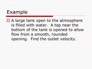
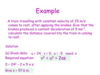
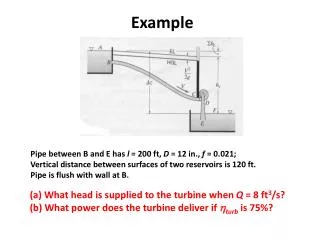
Example Pipe between B and E has l = 200 ft, D = 12 in., f = 0.021; Vertical distance between surfaces of two reservoirs is 120 ft. Pipe is flush with wall at B. (a) What head is supplied to the turbine when Q = 8 ft3/s? (b) What power does the turbine deliver if hturb is 75%?
Example To conserve water and energy, a “flow reducer” is installed in the shower head shown at the right. If the pressure at point (1) remains constant and all losses except for that in the flow reducer are neglected, determine the value of the loss coefficient (based on the velocity in the pipe) of the flow reducer, if it’s presence is to reduce the flow rate by a factor of two. Assume that the elevation difference between point (1) and the outlet is negligible. Write the energy equation before and after installation of the flow reducer, and solve for p1 in each case.
Before: Simplifications: By continuity:
After: Simplifications: Again, by continuity:
Given: Given: