Implementing IP Addressing Services
560 likes | 688 Vues
This chapter focuses on implementing IP addressing services, specifically configuring DHCP and NAT on Cisco routers, and enhancing routing protocols with RIPng for IPv6. It emphasizes the importance of DHCP in dynamically assigning IP addresses, which simplifies network management and eliminates the need for static assignments in dynamic environments. Additionally, it covers the DHCP operation, different address allocation mechanisms, and highlights the distinctions between DHCP and its predecessor, BOOTP. Finally, it discusses verifying DHCP configuration and operations to ensure efficient network functionality.

Implementing IP Addressing Services
E N D
Presentation Transcript
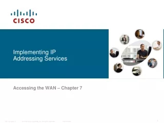
Implementing IP Addressing Services Accessing the WAN– Chapter 7
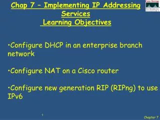
Objectives • Configure DHCP in an enterprise branch network • Configure NAT on a Cisco router • Configure new generation RIP (RIPng) to use IPv6
Introducing DHCP Every device that connects to a network needs an IP address. Network administrators assign static IP addresses to routers, servers, and other network devices whose locations (physical and logical) are not likely to change. Administrators enter static IP addresses manually when they configure devices to join the network. Static addresses also enable administrators to manage those devices remotely. However, computers in an organization often change locations, physically and logically. Administrators are unable to keep up with having to assign new IP addresses every time an employee moves to a different office or cubicle. Desktop clients do not require a static address. Instead, a workstation can use any address within a range of addresses. This range is typically within an IP subnet DHCP assigns IP addresses and other important network configuration information dynamically. Because desktop clients typically make up the bulk of network nodes, DHCP is an extremely useful and timesaving tool for network administrators. RFC 2131 describes DHCP.
Introducing DHCP Administrators typically prefer a network server to offer DHCP services, because these solutions are scalable and relatively easy to manage. However, in a small branch or SOHO location, a Cisco router can be configured to provide DHCP services without the need for an expensive dedicated server. A Cisco IOS feature set called Easy IP offers an optional, full-featured DHCP server.
DHCP Operation Providing IP addresses to clients is the most fundamental task performed by a DHCP server. DHCP includes three different address allocation mechanisms to provide flexibility when assigning IP addresses: Manual Allocation: The administrator assigns a pre-allocated IP address to the client and DHCP only communicates the IP address to the device. Automatic Allocation: DHCP automatically assigns a static IP address permanently to a device, selecting it from a pool of available addresses. There is no lease and the address is permanently assigned to a device. Dynamic Allocation: DHCP automatically dynamically assigns, or leases, an IP address from a pool of addresses for a limited period of time chosen by the server, or until the client tells the DHCP server that it no longer needs the address.
BOOTP vs. DHCP The Bootstrap Protocol (BOOTP), defined in RFC 951, is the predecessor of DHCP and shares some operational characteristics. BOOTP is a way to download address and boot configurations for diskless workstations. A diskless workstation does not have a hard drive or an operating system. For example, many automated cash register systems at your local supermarket are examples of diskless workstations Both DHCP and BOOTP are client/server based and use UDP ports 67 and 68. Those ports are still known as BOOTP ports.
BOOTP vs. DHCP There are three primary differences between DHCP and BOOTP: The main difference is that BOOTP was designed for manual pre-configuration of the host information in a server database, while DHCP allows for dynamic allocation of network addresses and configurations to newly attached hosts. DHCP allows for recovery and reallocation of network addresses through a leasing mechanism. Specifically, DHCP defines mechanisms through which clients can be assigned an IP address for a finite lease period. This lease period allows for reassignment of the IP address to another client later, or for the client to get another assignment if the client moves to another subnet. Clients may also renew leases and keep the same IP address. BOOTP does not use leases. BOOTP provides a limited amount of information to a host. DHCP provides additional IP configuration parameters, such as WINS and domain name
DHCP Server Configuration Cisco routers running Cisco IOS software provide full support for a router to act as a DHCP server. The Cisco IOS DHCP server assigns and manages IP addresses from specified address pools within the router to DHCP clients.
Verify DHCP Server Configuration To verify the operation of DHCP, use the show ip dhcp binding command. This command displays a list of all IP address to MAC address bindings that have been provided by the DHCP service. To verify that messages are being received or sent by the router, use the show ip dhcp server statistics command. This command displays count information regarding the number of DHCP messages that have been sent and received.
DHCP Client Configuration • Typically, small broadband routers for home use, such as Linksys routers, can be configured to connect to an ISP using a DSL or cable modem. In most cases, small home routers are set to acquire an IP address automatically from their ISPs. For example, the figure shows the default WAN setup page for a Linksys WRVS4400N router. Notice that the Internet connection type is set to Automatic Configuration - DHCP. This means that when the router is connected to a cable modem, for example, it is a DHCP client and requests an IP address from the ISP.
DHCP Client Configuration Cisco routers in SOHO and branch sites have to be configured in a similar manner. The method used depends on the ISP. However, in its simplest configuration, the Ethernet interface is used to connect to a cable modem. To configure an Ethernet interface as a DHCP client, the ip address dhcp command must be configured. In the figure, assume that an ISP has been configured to provide select customers with IP addresses from the 209.165.201.0 / 27 range. Theouput confirms the assigned address.
DHCP Relay In a complex hierarchical network, enterprise servers are usually contained in a server farm. These servers may provide DHCP, DNS, TFTP, and FTP services for the clients. The problem is that the network clients typically are not on the same subnet as those servers. Therefore, the clients must locate the servers to receive services and often these services are located using broadcast messages. In the figure, PC1 is attempting to acquire an IP address from the DHCP server located at 192.168.11.5. In this scenario router R1 is not configured as a DHCP server.
DHCP Relay A simpler solution is to configure the Cisco IOS helper address feature on intervening routers and switches. This solution enables routers to forward DHCP broadcasts to the DHCP servers. When a router forwards address assignment/parameter requests, it is acting as a DHCP relay agent. For example, PC1 would broadcast a request to locate a DHCP server. If router R1 were configured as a DHCP relay agent, it would intercept this request and forward it to the DHCP server located on subnet 192.168.11.0. To configure router R1 as a DHCP relay agent, you need to configure the nearest interface to the client with the ip helper-address interface configuration command. This command relays broadcast requests for key services to a configured address. Configure the IP helper address on the interface receiving the broadcast. Router R1 is now configured as a DHCP relay agent. It accepts broadcast requests for the DHCP service and then forwards them as a unicast to the IP address 192.168.11.5.
DHCP Configuration with SDM Cisco routers can also be configured as a DHCP server using SDM. In this example, router R1 will be configured as the DHCP server on the Fa0/0 and Fa0/1interfaces. The DHCP server function is enabled under Additional Tasks in the Configure tab. From the list of tasks, click on the DHCP folder and then select DHCP Pools to add a new pool. Click Add to create the new DHCP pool.
DHCP Configuration with SDM The Add DHCP Pool window contains the options you need to configure the DHCP IP address pool. The IP addresses that the DHCP server assigns are drawn from a common pool. To configure the pool, specify the starting and ending IP addresses of the range.
DHCP Configuration with SDM This screen provides you with a summary of the pools configured on your router. In this example, there have been two pools configured, one for each of the Fast Ethernet interfaces on the R1 router.
Troubleshooting DHCP DHCP problems can arise for a multitude of reasons, such as software defects in operating systems, NIC drivers, or DHCP/BOOTP relay agents, but the most common are configuration issues. Because of the number of potentially problematic areas, a systematic approach to troubleshooting is required. show ip dhcp conflict show int
Verify DHCP Relay Follow these steps to verify the router configuration: Step 1. Verify that the ip helper-address command is configured on the correct interface. It must be present on the inbound interface of the LAN containing the DHCP client workstations and must be directed to the correct DHCP server. In the figure, the output of the show running-config command verifies that the DHCP relay IP address is referencing the DHCP server address at 192.168.11.5. Step 2. Verify that the global configuration command no service dhcp has not been configured. This command disables all DHCP server and relay functionality on the router. The command service dhcp does not appear in the configuration, because it is the default configuration.
Private and Public Addressing All public Internet addresses must be registered with a Regional Internet Regiestry (RIR). Organizations can lease public addresses from an ISP. Only the registered holder of a public Internet address can assign that address to a network device. You may have noticed that all the examples in this course use a somewhat restricted number of IP addresses. You may also have noticed the similarity between these numbers and numbers you have used in a small network to view the setup web pages of many brands of printers, DSL and cable routers, and other peripherals. These are reserved private Internet addresses drawn from the three blocks shown in the figure. These addresses are for private, internal network use only. Packets containing these addresses are not routed over the Internet, and are referred to as non-routable addresses. RFC 1918 provides details. Unlike public IP addresses, private IP addresses are a reserved block of numbers that can be used by anyone. That means two networks, or two million networks, can each use the same private addresses. To prevent addressing conflicts, routers must never route private IP addresses. To protect the public Internet address structure, ISPs typically configure the border routers to prevent privately addressed traffic from being forwarded over the Internet.
What is NAT? NAT has many uses, but its key use is to save IP addresses by allowing networks to use private IP addresses. NAT translates non-routable, private, internal addresses into routable, public addresses. NAT has an added benefit of adding a degree of privacy and security to a network because it hides internal IP addresses from outside networks. A NAT-enabled device typically operates at the border of a stub network. In our example, R2 is the border router. A stub network is a network that has a single connection to its neighbor network. As seen from the ISP, R2 forms a stub network.
What is NAT? Inside local address - Usually not an IP address assigned by a RIR or service provider and is most likely an RFC 1918 private address. In the figure, the IP address 192.168.10.10 is assigned to the host PC1 on the inside network. Inside global address - Valid public address that the inside host is given when it exits the NAT router. When traffic from PC1 is destined for the web server at 209.165.201.1, router R2 must translate the address. In this case, IP address 209.165.200.226 is used as the inside global address for PC1. Outside global address - Valid public IP address assigned to a host on the Internet. For example, the web server is reachable at IP address 209.165.201.1. Outside local address - The local IP address assigned to a host on the outside network. In most situations, this address will be identical to the outside global address of that outside device.
What is NAT? Dynamic Mapping and Static Mapping There are two types of NAT translation: dynamic and static. Dynamic NAT uses a pool of public addresses and assigns them on a first-come, first-served basis. When a host with a private IP address requests access to the Internet, dynamic NAT chooses an IP address from the pool that is not already in use by another host. This is the mapping described so far. Static NAT uses a one-to-one mapping of local and global addresses, and these mappings remain constant. Static NAT is particularly useful for web servers or hosts that must have a consistent address that is accessible from the Internet. These internal hosts may be enterprise servers or networking devices. Both static and dynamic NAT require that enough public addresses are available to satisfy the total number of simultaneous user sessions.
What is NAT? NAT Overload NAT overloading (sometimes called Port Address Translation or PAT) maps multiple private IP addresses to a single public IP address or a few addresses. This is what most home routers do. With NAT overloading, multiple addresses can be mapped to one or to a few addresses because each private address is also tracked by a port number. When a client opens a TCP/IP session, the NAT router assigns a port number to its source address. NAT overload ensures that clients use a different TCP port number for each client session with a server on the Internet.
NAT advantages and disadvantages NAT provides many benefits and advantages. However, there are some drawbacks to using NAT, including the lack of support for some types of traffic.
Configure NAT on a Cisco Router Configuring static NAT translations is a simple task. You need to define the addresses to translate and then configure NAT on the appropriate interfaces.Packets arriving on an inside interface from the identified IP address are subject to translation. Packets arriving on an outside interface addressed to the identified IP address are subject to translation
Configure NAT on a Cisco Router • While static NAT provides a permanent mapping between an internal address and a specific public address, dynamic NAT maps private IP addresses to public addresses. These public IP addresses come from a NAT pool.
Configure NAT on a Cisco Router • There are two possible ways to configure overloading, depending on how the ISP allocates public IP addresses. In the first instance, the ISP allocates one public IP address to the organization, and in the other, it allocates more than one public IP address.
Describe how to configure port forwarding on a Cisco Router • Port forwarding (sometimes referred to as tunneling) is the act of forwarding a network port from one network node to another. This technique can allow an external user to reach a port on a private IP address (inside a LAN) from the outside through a NAT-enabled router
Verifying and Troubleshoot NAT Configurations Verifying NAT and NAT Overload It is important to verify NAT operation. There are several useful router commands to view and clear NAT translations. One of the most useful commands when verifying NAT operation is the show ip nat translations command. Before using the show commands to verify NAT, you must clear any dynamic translation entries that might still be present, because by default, dynamic address translations time out from the NAT translation table after a period of non-use.
Verifying and Troubleshoot NAT Configurations The show ip nat statistics command displays information about the total number of active translations, NAT configuration parameters, how many addresses are in the pool, and how many have been allocated. In the figure, the hosts have initiated web traffic as well as ICMP traffic.
Verifying and Troubleshoot NAT Configurations Follow these steps to verify that NAT is operating as expected: Step 1. Based on the configuration, clearly define what NAT is supposed to achieve. This may reveal a problem with the configuration. Step 2. Verify that correct translations exist in the translation table using the show ip nat translations command. Step 3.Use the clear and debug commands to verify that NAT is operating as expected. Check to see if dynamic entries are recreated after they are cleared. Step 4. Review in detail what is happening to the packet, and verify that routers have the correct routing information to move the packet. Use the debug ip nat command to verify the operation of the NAT feature by displaying information about every packet that is translated by the router.
Reasons for Using IPv6 To comprehend the IP addressing issues facing network administrators today, consider that the IPv4 address space provides approximately 4,294,967,296 unique addresses. Of these, only 3.7 billion addresses are assignable because the IPv4 addressing system separates the addresses into classes and reserves addresses for multicasting, testing, and other specific uses. Based on figures as recent as January 2007, about 2.4 billion of the available IPv4 addresses are already assigned to end users or ISPs. That leaves roughly 1.3 billion addresses still available from the IPv4 address space. Despite this seemingly large number, IPv4 address space is running out.
Reasons for Using IPv6 Movement to change from IPv4 to IPv6 has already begun, particularly in Europe, Japan, and the Asia-Pacific region. These areas are exhausting their allotted IPv4 addresses, which makes IPv6 all the more attractive and necessary. Japan officially started the move in 2000 when the Japanese government mandated the incorporation of IPv6 and set a deadline of 2005 to upgrade existing systems in every business and public sector. Korea, China, and Malaysia have launched similar initiatives. In 2002, the European Community IPv6 Task Force forged a strategic alliance to foster IPv6 adoption worldwide. The North American IPv6 Task Force has set out to engage the North American markets to adopt IPv6. The first significant North American advances are coming from the U.S. Department of Defense (DoD). Looking into the future and knowing the advantages of IP-enabled devices, DoD mandated, as early as 2003, that all new equipment purchased not only be IP-enabled, but also be IPv6-capable. In fact, all U.S. government agencies must start using IPv6 across their core networks by 2008, and the agencies are working to meet that deadline.
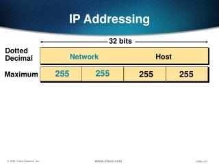
Reasons for Using IPv6 Pv6 Address Representation You know the 32-bit IPv4 address as a series of four 8-bit fields, separated by dots. However, larger 128-bit IPv6 addresses need a different representation because of their size. IPv6 addresses use colons to separate entries in a series of 16-bit hexadecimal.
Reasons for Using IPv6 Using the "::" notation greatly reduces the size of most addresses as shown. An address parser identifies the number of missing zeros by separating any two parts of an address and entering 0s until the 128 bits are complete.
IPv6 Global Unicast Addressing IPv6 has an address format that enables aggregation upward eventually to the ISP. Global unicast addresses typically consists of a 48-bit global routing prefix and a 16-bit subnet ID. Individual organizations can use a 16-bit subnet field to create their own local addressing hierarchy. This field allows an organization to use up to 65,535 individual subnets.
IPv6 Address Management IPv6 addresses use interface identifiers to identify interfaces on a link. Think of them as the host portion of an IPv6 address. Interface identifiers are required to be unique on a specific link. Interface identifiers are always 64 bits and can be dynamically derived from a Layer 2 address (MAC). You can assign an IPv6 address ID statically or dynamically: Static assignment using a manual interface ID Static assignment using an EUI-64 interface ID Stateless autoconfiguration DHCP for IPv6 (DHCPv6)
IPv6 Address Management To configure an IPv6 address on a Cisco router interface and enable IPv6 processing using EUI-64 on that interface, use the ipv6 address ipv6-prefix/prefix-length eui-64 command in interface configuration mode. ipv6 addressIPv6-address[/prefix length]interface command. RouterX(config-if)#ipv6 address 2001:DB8:2222:7272::/64 eui-64
IPv6 Transition Strategies The transition from IPv4 does not require upgrades on all nodes at the same time. Many transition mechanisms enable smooth integration of IPv4 and IPv6. Other mechanisms that allow IPv4 nodes to communicate with IPv6 nodes are available. Different situations demand different strategies. The figure illustrates the richness of available transition strategies. Recall the advice: "Dual stack where you can, tunnel where you must." These two methods are the most common techniques to transition from IPv4 to IPv6. Dual Stacking Dual stacking is an integration method in which a node has implementation and connectivity to both an IPv4 and IPv6 network. This is the recommended option and involves running IPv4 and IPv6 at the same time. Router and switches are configured to support both protocols, with IPv6 being the preferred protocol. Tunneling The second major transition technique is tunneling. There are several tunneling techniques available, including: Manual IPv6-over-IPv4 tunneling - An IPv6 packet is encapsulated within the IPv4 protocol. This method requires dual-stack routers. Dynamic 6to4 tunneling - Automatically establishes the connection of IPv6 islands through an IPv4 network, typically the Internet. It dynamically applies a valid, unique IPv6 prefix to each IPv6 island, which enables the fast deployment of IPv6 in a corporate network without address retrieval from the ISPs or registries
IPv6 Transition Strategies Other less popular tunneling techniques that are beyond the scope of this course include: Intra-Site Automatic Tunnel Addressing Protocol (ISATAP) tunneling - Automatic overlay tunneling mechanism that uses the underlying IPv4 network as a link layer for IPv6. ISATAP tunnels allow individual IPv4 or IPv6 dual-stack hosts within a site to communicate with other such hosts on a virtual link, creating an IPv6 network using the IPv4 infrastructure. Teredo tunneling - An IPv6 transition technology that provides host-to-host automatic tunneling instead of gateway tunneling. This approach passes unicast IPv6 traffic when dual-stacked hosts (hosts that are running both IPv6 and IPv4) are located behind one or multiple IPv4 NATs. NAT-Protocol Translation (NAT-PT) Cisco IOS Release 12.3(2)T and later (with the appropriate feature set) also include NAT-PT between IPv6 and IPv4. This translation allows direct communication between hosts that use different versions of the IP protocol. These translations are more complex than IPv4 NAT. At this time, this translation technique is the least favorable option and should be used as a last resort.
IPv6 Dual Stacking Dual Stacking Dual stacking is an integration method in which a node has implementation and connectivity to both an IPv4 and IPv6 network. This is the recommended option and involves running IPv4 and IPv6 at the same time. Router and switches are configured to support both protocols, with IPv6 being the preferred protocol.
IPv6 Tunneling The concept of IPv6 tunneling • The second major transition technique is tunneling. There are several tunneling techniques available, including: • Manual IPv6-over-IPv4 tunneling - An IPv6 packet is encapsulated within the IPv4 protocol. This method requires dual-stack routers. • Dynamic 6to4 tunneling - Automatically establishes the connection of IPv6 islands through an IPv4 network, typically the Internet. It dynamically applies a valid, unique IPv6 prefix to each IPv6 island, which enables the fast deployment of IPv6 in a corporate network without address retrieval from the ISPs or registries.
Configure New Generation RIP (RIPng) to use IPv6 IPv6 routes use the same protocols and techniques as IPv4. Although the addresses are longer, the protocols used in routing IPv6 are simply logical extensions of the protocols used in IPv4. RFC 2080 defines Routing Information Protocol next generation (RIPng) as a simple routing protocol based on RIP. RIPng is no more or less powerful than RIP, however, it provides a simple way to bring up an IPv6 network without having to build a new routing protocol. RIPng is a distance vector routing protocol with a limit of 15 hops that uses split horizon and poison reverse updates to prevent routing loops. Its simplicity comes from the fact that it does not require any global knowledge of the network. Only neighboring routers exchange local messages.
Configure New Generation RIP (RIPng) to use IPv6 There are two basic steps to activate IPv6 on a router. First, you must activate IPv6 traffic-forwarding on the router, and then you must configure each interface that requires IPv6.
Summary • Dynamic Host Control Protocol (DHCP) This is a means of assigning IP address and other configuration information automatically. • DHCP operation • 3 different allocation methods • Manual • Automatic • Dynamic • Steps to configure DHCP • Define range of addresses • Create DHCP pool • Configure DHCP pool specifics