Ferromagnetic Nanoparticles
Ferromagnetic Nanoparticles. KE-31.5530 Nanoparticles P Marra Fabrizio. Outline. Introduction Component of the Nanoparticles Experimental Procedures Conclusion. Introduction.

Ferromagnetic Nanoparticles
E N D
Presentation Transcript
FerromagneticNanoparticles KE-31.5530 Nanoparticles P Marra Fabrizio Aalto University - School of Science and Technology
Outline • Introduction • Component of the Nanoparticles • ExperimentalProcedures • Conclusion Aalto University - School of Science and Technology
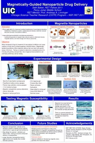
Introduction • Magnetic nanoparticles are currently being investigated because of their numerous applications in several fields such as • Magnetic fluids • Medicine • Magnetic resonance imaging • Data storage • Sensing • Water remediation • Itisoften necessary to coat their surface with an organic or inorganic shell, in order to protect them from chemical degradation or agglomeration according to the environments in which they will be used • The coating can also be performed in order to add new functionalities to the magnetic core, such as biological stealth, optical properties, catalytic or adsorbing capacity Aalto University - School of Science and Technology
The aim is to analyze the behavior of nanoparticleswith a magnetic core • The physical and chemical properties depend on • The method of synthesis • The chemical structure • Particle size: 10-300 nm Titania Magnetite Silica Aalto University - School of Science and Technology
The experimental phase in the production ofparticles, can be divided into three steps: • Production of ferromagnetic particles • Coating with silica • Coating with titanium dioxide being anatase Aalto University - School of Science and Technology
Magnetic properties • If the structure is cubic body centered thecapacity of iron ore is ferromagnetic • Magnetic properties you have only to overlap of ψ of electron with spin decoupled Aalto University - School of Science and Technology
Magnetic properties • MAGNETITE: • The magnetic properties of magnetite aredue to divalent iron ions that give unlike the magnetic moment of ions trivalent who have zero magnetic moment. Aalto University - School of Science and Technology
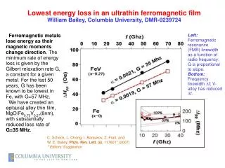
Temperature Change • The cubic form of the ferrite-α ferromagnetic is stablefrom to 768°C (). Over there no permanent magnetization • This temperature is defined as follows: • C is a constant characteristic of the material • ρ density • TheTc Curie temperature (K) T= 858°C Aalto University - School of Science and Technology
Preliminary • Preparation of solutions for the heartferromagnetic • to 0.85 M • Composite of 21.45 g of + 66 ml 2M +227 ml of distilled water + 44 ml of 1M Aalto University - School of Science and Technology
In solution with 66 ml and 227 ml of distilled water Add 44 ml of1 M Weigh 21.42 g Aalto University - School of Science and Technology
PH acid • Colour change for complex formation between the ions Fe3+and SO2-3 according to the reaction • Add 1 liter of 0.85 M, which is added while stirring with a metering pump (peristaltic) set at 10 ml/min • pH >> Formation of iron hydroxide , and gelatinous insoluble. Aalto University - School of Science and Technology
It is obtained by heating the oxide hydrate and its anhydrous form • Calcine the trioxide to 1400°C you get (Magnetite) dispersed in solution sour composed of 30% 0.1 M from 2 to 24 h • We carry out a treatment with ultrasonic bath for 30 min • VolumeHCl • Weight • Weight Aalto University - School of Science and Technology
Mixing of chemicals Aalto University - School of Science and Technology
Comments • The final solution after 36 h ofinactivity • The color is black Aalto University - School of Science and Technology
SilicaCoating • Interposes a membrane to prevent degradation of photocatalyticproperties • The coating is produced using a solution of distilled water and sodium silicate • Followed by calcination at 400-450°C DEPARTURE OF POWDERSODIUM SILICATE Aalto University - School of Science and Technology
This eliminates an excess solution through the use of a supermagnet able to keep the nanoparticles at the bottom of the beaker. Aalto University - School of Science and Technology
We tested the properties of ferromagnetic nanoparticles before coatingWe tested the properties of ferromagnetic nanoparticles before coating Aalto University - School of Science and Technology
Dilute nanoparticles in 2 liters of distilled water • The silicate solution was prepared con 1 liter of distilled water and 31.5 g of , start agitation for 45 min. • The two solutions were combined with a peristaltic pump with a flow rate of 2 g/l • Finally, the only solution they put in agitation for more than 24 h. Aalto University - School of Science and Technology
Calcinationat450°C, after the solution dried in an oven at95°C Aalto University - School of Science and Technology
Dust ofFerromagnetic Nanoparticleswith SilicaCoating Supermagnet Aalto University - School of Science and Technology
Titania Coating • Dilution in 100 ml of distilled water; • Added a solution of water and titanium dioxide (125ml) • Mechanical agitation 24h (mixing 2 solutions) • Beaker in an oven at 94°C for drying • Calcination at 450°C Aalto University - School of Science and Technology
We tested the properties of ferromagnetic nanoparticles even after being coated Aalto University - School of Science and Technology
PhotocatalyticDegradation • Radiation can be catalysts for chemical reactions • The radiation must be extremely fast • The radiation affects a chemical species, is the fraction absorbed and not transmitted • To increase the speed of reaction are used Catalysts. • If the catalyst is solid type is spoken of heterogeneous catalysis (gas and liquid phase) • We summarize the process in 5 independent steps: • Transfer of reagents from the fluid phase to the surface • Adsorption of at least one reagent • Reaction in the adsorbed phase • Desorption of products • Remove the products from the region at the interface Aalto University - School of Science and Technology
HeterogeneousCatalysis • Process of heterogeneous photocatalysis to remove organic compounds • Aqueous solution of dyes organic (Orange II) as an example of waste water from the textile industry Spectrophotometer DR LANGE LASA 100 Aalto University - School of Science and Technology
The advantages of this technology • Promotes the chemical transformation of the contaminant and not simply a phase change • To the pollution there is a complete mineralization • Usually do not generate sludge, which in turn would require a process of treatment • No reaction products are generated or are formed in low concentration • They consume less energy than other methods • They allow you to transform refractory contaminants in products treated with methods economic as biological treatment Aalto University - School of Science and Technology
Experimental Work • Oxidation by UV radiation of parameters: • Agitationsystem • Addition of ferromagnetic particles with coating of titanium dioxide as photocatalyst • Measurement procedure of killing photocatalytic: • We lost the Orange II in the amount of 0.02g Aalto University - School of Science and Technology
These weredissolved in 200 mldistilled water • Mechanicallystirred solution is addition of 1 g Aalto University - School of Science and Technology
PhotocatalyticReactor • The reaction occurs in the presence of UV rays • We used a reactor of the type STR (stirred tank reactor) • The photocatalytic reactor should be transparent and resistant to UV radiation and chemical attack Aalto University - School of Science and Technology
Let the solution stirs in the beaker with under a lamp UV λ = 264 nm • From the beaker were taken periodically with an interval of time of 20 min, 5 ml of solution to be filtered with a filter-syringe to measure the absorbance Aalto University - School of Science and Technology
We have considered the following relation between the concentration and absorbance • From this can actually calculate the concentration, replaced from time to time the absorbance in the unknown Aalto University - School of Science and Technology
PhotocatalyticAbatementA PhotocatalyticAbatementB • A>B • Change = 5.81% Aalto University - School of Science and Technology
Comparison with Literature • In summary, we prepared core-shell photocatalyticnanoparticles with a higher photocatalytic activity and a fast magnetic separability • The structures were produced by converting a Solgeland following calcination to have a layer of anatasenanocrystals that have been linked to the surface of /magnetic core Aalto University - School of Science and Technology
Inserts in c. & d. showsthemorphologychangeofcalcined // calcined/ / Aalto University - School of Science and Technology
SEM images /(meandiameter = 311.0 nm) // (meandiameter = 340.0 nm) Calcinedparticles//(diameterAverage = 338.7 nm) Aalto University - School of Science and Technology
Absorption spectrum of RhB solutionin the presence of calcinedparticlesof// underexposure toUV rays Photocatalytic performance of various samples = UV = / / = / = P25 = / = Aalto University - School of Science and Technology
TEM image of // after calcinationat 500°C with different amount of precursor • 0ml (mean diameter = 252.9 nm) • 150 ml (mean diameter = 278.2 nm) • 250 ml (mean diameter = 282.4 nm) Aalto University - School of Science and Technology
Effect of the thickness of titanium dioxide Decomposition reaction The apparent rate of calcined // Aalto University - School of Science and Technology
Photocatalytic efficiency ≃ Degussa P25 • The photocatalytic activity can be causedbytwofactors • The small size of anatasenanocrystals formedduring the calcination of the shell (10 nm) • /structure improves the photocatalyticefficiency (the has essentially nocontributionin the activity photocatalytic) Aalto University - School of Science and Technology
References • Marra Fabrizio and Mirotta Nicola/ ‘Laboratory Work on γ-//’, University of ‘La Sapienza di Roma’ 2011 • SébastienAbramson/ ‘Nanometriccore-shell-shell γ-//particles’, 29 August 2008 • MiaomiaoYe/‘Magnetically Recoverable Core–Shell Nanocomposites with Enhanced PhotocatalyticActivity’, 2010 Aalto University - School of Science and Technology
Thanks for Your Attenction Aalto University - School of Science and Technology