Download
1 / 21
240 likes | 625 Vues
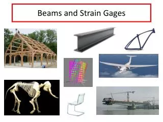
Beams and Strain Gages. Cantilever Beam One End Fixed , One End Free. Everything is a Spring Beams Bend When Loaded. Tip Load Creates Internal Moments and Forces. Isolate a section of the beam (NOT physically separated). x-section. F. F. M(x). x. L-x. V(x). x. V.

E N D
Tip Load Creates Internal Moments and Forces Isolate a section of the beam (NOT physically separated) x-section F F M(x) x L-x V(x) x V At any point along the beam, there is a reaction force and moment (from contact with material to the left of x-section) to maintain static equilibrium. Distribution of moment, M, and (shear) force, V, along beam
How Does the Force Deform the Beam? DaVinci-1493 "Of bending of the springs: If a straight spring is bent, it is necessary that its convex part become thinner and its concave part, thicker. This modification is pyramidal, and consequently, there will never be a change in the middle of the spring. You shall discover, if you consider all of the aforementioned modifications, that by taking part 'ab' in the middle of its length and then bending the spring in a way that the two parallel lines, 'a' and 'b' touch a the bottom, the distance between the parallel lines has grown as much at the top as it has diminished at the bottom. Therefore, the center of its height has become much like a balance for the sides. And the ends of those lines draw as close at the bottom as much as they draw away at the top. From this you will understand why the center of the height of the parallels never increases in 'ab' nor diminishes in the bent spring at 'co.' Galileo-1638 Incorrectly claimed that the root of beam was in tension. (give him a break-Newton was born a year after he died)
Consider a Free-Free Beam Loaded by a Moment For long, thin beams loaded by a transverse force, deformation is predominately due to internal moment as compared to internal force. (Euler-Bernoulli Beam Assumption) M M neutral surface The upper portion is in compression. The lower portion is in tension. ‘neutral surface’ does not change in length
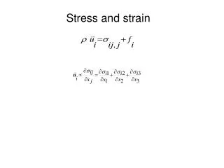
Transverse Force Causes Axial Deformation How do we relate Load to Deformation? Load Stress Strain Deformation
Stress is a Quantitative Measure of Load Acting on a Material In general stress is a tensor quantity -> represented by a matrix of scalars stress matrix
For Simple Cases, Stress Can Be Represented by a Single Scalar Component* Force applied normal to a cross-section (axially) F F Ao average normal stress over the cross-section F s = Ao *In the stress matrix, only one term will have significant nonzero magnitude. The other eight terms ~ 0. [s] s11 = F/A0
Strain = Normalized Deformation x e = Lo x Lo Average normal engineering strain over the cross-section F F Ao
How are Normal Stress and Strain Related? Uniaxial Tension Test test specimen extensometer (measures strain) load cell (measures force)
s Linear Elastic Behavior When loading is released, material returns to its original length. sy yield stress slope = E (Young’s Modulus) property of a material Aluminum (6061-T6): E = 40 ksi = 275 MPa linearelastic deformation e
s Typical Ductile Material su ultimate tensile strength “necking” fracture stress sy yield stress “strain hardening” linearelastic deformation uniform plastic deformation nonuniform plastic deformation e
Bending (Normal) Stress in a Beam Will derive this in Mechanics of Solids and Structures Mz = Moment about the z-axis (out of page) acting on the x-section. Constant over the x-section. y = distance from neutral surface (in y-direction). Izz = area moment of inertia of the x-section about z-axis. y σ(-compression) Mz Mz x Neutral surface passes through the centroid of cross-section O Stress distribution is linear over x-section σ(+tension) Specified cross-section
Area Moment of Inertia Concept-measure of how hard a cross-section is to rotate. y y h z O = centroid z O = centroid (always lies on lines of symmetry) b *effect from changing h >> b
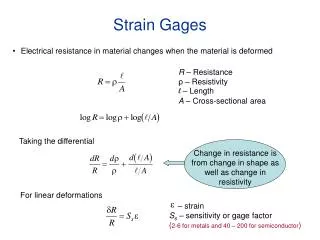
Strain Gages Measure Axial Strain The resistance of gage changes as it stretches or compresses. Strain gages must be well attached to the surface of a material so that it deforms as the material deforms. 6.4 x 4.3 mm
Strain is Proportional to the Change of Resistance of the Gage R is nominal resistance GF is gage factor-a calibration constant. Ourshave GF = 2.1 Change in resistance is very small-need a circuit to measure.
Wheatstone Bridge + - Invented by Samuel Hunter Christie ~1833 Improved by Sir Charles Wheatstone ~1843
A Possible Setup R4 Strain gage Proportional to strain !
In Practice, Why Do We Want Variable R? Strain gage
Now That You Know About Beams and Strain Gages You Can Make a Calibrated Scale F Relate the force applied to the strain* Compare analytical predictions to measurements * depends on both geometry and material