z Transform Signal and System Analysis
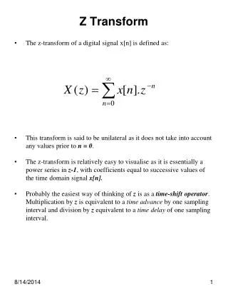
z Transform Signal and System Analysis. Chapter 12. Block Diagrams and Transfer Functions.


z Transform Signal and System Analysis
E N D
Presentation Transcript
z Transform Signal and System Analysis Chapter 12
Block Diagrams and Transfer Functions Just as with CT systems, DT systems are conveniently described by block diagrams and transfer functions can be determined from them. For example, from this DT system block diagram the difference equation can be determined. M. J. Roberts - All Rights Reserved. Edited by Dr. Robert Akl
Block Diagrams and Transfer Functions From a z-domain block diagram the transfer function can be determined. M. J. Roberts - All Rights Reserved. Edited by Dr. Robert Akl
Block Diagram Reduction All the techniques for block diagram reduction introduced with the Laplace transform apply exactly to z transform block diagrams. M. J. Roberts - All Rights Reserved. Edited by Dr. Robert Akl
System Stability A DT system is stable if its impulse response is absolutely summable. That requirement translates into the z-domain requirement that all the poles of the transfer function must lie in the open interior of the unit circle. M. J. Roberts - All Rights Reserved. Edited by Dr. Robert Akl
System Interconnections Cascade Parallel M. J. Roberts - All Rights Reserved. Edited by Dr. Robert Akl
System Interconnections M. J. Roberts - All Rights Reserved. Edited by Dr. Robert Akl
Responses to Standard Signals If the system transfer function is the z transform of the unit-sequence response is which can be written in partial-fraction form as If the system is stable the transient term, , dies out and the steady-state response is . M. J. Roberts - All Rights Reserved. Edited by Dr. Robert Akl
Responses to Standard Signals Let the system transfer function be Then and Let the constant, K be 1 - p. Then M. J. Roberts - All Rights Reserved. Edited by Dr. Robert Akl
Responses to Standard Signals Unit Sequence Response One-Pole System M. J. Roberts - All Rights Reserved. Edited by Dr. Robert Akl
Responses to Standard Signals Unit Sequence Response Two-Pole System M. J. Roberts - All Rights Reserved. Edited by Dr. Robert Akl
Responses to Standard Signals If the system transfer function is the z transform of the response to a suddenly-applied sinusoid is The system response can be written as and, if the system is stable, the steady-state response is a DT sinusoid with, generally, different magnitude and phase. M. J. Roberts - All Rights Reserved. Edited by Dr. Robert Akl
Pole-Zero Diagrams and Frequency Response For a stable system, the response to a suddenly-applied sinusoid approaches the response to a true sinusoid (applied for all time). M. J. Roberts - All Rights Reserved. Edited by Dr. Robert Akl
Pole-Zero Diagrams and Frequency Response Let the transfer function of a DT system be M. J. Roberts - All Rights Reserved. Edited by Dr. Robert Akl
Pole-Zero Diagrams and Frequency Response M. J. Roberts - All Rights Reserved. Edited by Dr. Robert Akl
The Jury Stability Test Let a transfer function be in the form, where Form the “Jury” array M. J. Roberts - All Rights Reserved. Edited by Dr. Robert Akl
The Jury Stability Test The third row is computed from the first two by The fourth row is the same set as the third row except in reverse order. Then the c’s are computed from the b’s in the same way the b’s are computed from the a’s. This continues until only three entries appear. Then the system is stable if M. J. Roberts - All Rights Reserved. Edited by Dr. Robert Akl
Root Locus Root locus methods for DT systems are like root locus methods for CT systems except that the interpretation of the result is different. CT systems: If the root locus crosses into the right half-plane the system goes unstable at that gain. DT systems: If the root locus goes outside the unit circle the system goes unstable at that gain. M. J. Roberts - All Rights Reserved. Edited by Dr. Robert Akl
Simulating DT Systems with DT Systems The ideal simulation of a CT system by a DT system would have the DT system’s excitation and response be samples from the CT system’s excitation and response. But that design goal is never achieved exactly in real systems at finite sampling rates. M. J. Roberts - All Rights Reserved. Edited by Dr. Robert Akl
Simulating DT Systems with DT Systems One approach to simulation is to make the impulse response of the DT system be a sampled version of the impulse response of the CT system. With this choice, the response of the DT system to a DT unit impulse consists of samples of the response of the CT system to a CT unit impulse. This technique is called impulse-invariant design. M. J. Roberts - All Rights Reserved. Edited by Dr. Robert Akl
Simulating DT Systems with DT Systems When the impulse response of the DT system is a sampled version of the impulse response of the CT system but the unit DT impulse is not a sampled version of the unit CT impulse. A CT impulse cannot be sampled. First, as a practical matter the probably of taking a sample at exactly the time of occurrence of the impulse is zero. Second, even if the impulse were sampled at its time of occurrence what would the sample value be? The functional value of the impulse is not defined at its time of occurrence because the impulse is not an ordinary function. M. J. Roberts - All Rights Reserved. Edited by Dr. Robert Akl
Simulating DT Systems with DT Systems In impulse-invariant design, even though the impulse response is a sampled version of the CT system’s impulse response that does not mean that the response to samples from any arbitrary excitation will be a sampled version of the CT system’s response to that excitation. All design methods for simulating CT systems with DT systems are approximations and whether or not the approximation is a good one depends on the design goals. M. J. Roberts - All Rights Reserved. Edited by Dr. Robert Akl
Sampled-Data Systems Real simulation of CT systems by DT systems usually sample the excitation with an ADC, process the samples and then produce a CT signal with a DAC. M. J. Roberts - All Rights Reserved. Edited by Dr. Robert Akl
Sampled-Data Systems An ADC simply samples a signal and produces numbers. A common way of modeling the action of a DAC is to imagine the DT impulses in the DT signal which drive the DAC are instead CT impulses of the same strength and that the DAC has the impulse response of a zero-order hold. M. J. Roberts - All Rights Reserved. Edited by Dr. Robert Akl
Sampled-Data Systems The desired equivalence between a CT and a DT system is illustrated below. The design goal is to make look as much like as possible by choosing h[n] appropriately. M. J. Roberts - All Rights Reserved. Edited by Dr. Robert Akl
Sampled-Data Systems Consider the response of the CT system notto the actual signal, x(t), but rather to an impulse-sampled version of it, The response is where and the response at the nth multiple of is The response of a DT system with to the excitation, is M. J. Roberts - All Rights Reserved. Edited by Dr. Robert Akl
Sampled-Data Systems The two responses are equivalent in the sense that the values at corresponding DT and CT times are the same. M. J. Roberts - All Rights Reserved. Edited by Dr. Robert Akl
Sampled-Data Systems Modify the CT system to reflect the last analysis. Then multiply the impulse responses of both systems by M. J. Roberts - All Rights Reserved. Edited by Dr. Robert Akl
Sampled-Data Systems In the modified CT system, In the modified DT system, where and h(t) still represents the impulse response of the original CT system. Now let approach zero. This is the response, , of the original CT system. M. J. Roberts - All Rights Reserved. Edited by Dr. Robert Akl
Sampled-Data Systems Summarizing, if the impulse response of the DT system is chosen to be then, in the limit as the sampling rate approaches infinity, the response of the DT system is exactly the same as the response of the CT system. Of course the sampling rate can never be infinite in practice. Therefore this design is an approximation which gets better as the sampling rate is increased. M. J. Roberts - All Rights Reserved. Edited by Dr. Robert Akl
Digital Filters • Digital filter design is simply DT system design applied to filtering signals • A popular method of digital filter design is to simulate a proven CT filter design • There many design approaches each of which yields a better approximation to the ideal as the sampling rate is increased M. J. Roberts - All Rights Reserved. Edited by Dr. Robert Akl
Digital Filters • Practical CT filters have infinite-duration impulse responses, impulse responses which never actually go to zero and stay there • Some digital filter designs produce DT filters with infinite-duration impulse responses and these are called IIR filters • Some digital filter designs produce DT filters with finite-duration impulse responses and these are called FIR filters M. J. Roberts - All Rights Reserved. Edited by Dr. Robert Akl
Digital Filters • Some digital filter design methods use time-domain approximation techniques • Some digital filter design methods use frequency-domain approximation techniques M. J. Roberts - All Rights Reserved. Edited by Dr. Robert Akl
Digital Filters Impulse and Step Invariant Design M. J. Roberts - All Rights Reserved. Edited by Dr. Robert Akl
Digital Filters Impulse and Step Invariant Design Impulse invariant: Sample Step invariant: Sample M. J. Roberts - All Rights Reserved. Edited by Dr. Robert Akl
Digital Filters Impulse and Step Invariant Design Impulse invariant approximation of the one-pole system, yields M. J. Roberts - All Rights Reserved. Edited by Dr. Robert Akl
Digital Filters Impulse and Step Invariant Design Let a be one and let in Digital Filter Impulse Response CT Filter Impulse Response M. J. Roberts - All Rights Reserved. Edited by Dr. Robert Akl
Digital Filters Impulse and Step Invariant Design Step response of Notice scale difference Digital Filter Step Response CT Filter Step Response M. J. Roberts - All Rights Reserved. Edited by Dr. Robert Akl
Digital Filters Why is the impulse response exactly right while the step response is wrong? This design method forces an equality between the impulse strength of a CT excitation, a unit CT impulse at zero, and the impulse strength of the corresponding DT signal, a unit DT impulse at zero. It also makes the impulse response of the DT system, h[n], be samples from the impulse response of the CT system, h(t). M. J. Roberts - All Rights Reserved. Edited by Dr. Robert Akl
Digital Filters A CT step excitation is not an impulse. So what should the correspondence between the CT and DT excitations be now? If the step excitation is sampled at the same rate as the impulse response was sampled, the resulting DT signal is the excitation of the DT system and the response of the DT system is the sum of the responses to all those DT impulses. M. J. Roberts - All Rights Reserved. Edited by Dr. Robert Akl
Digital Filters If the excitation of the CT system were a sequence of CT unit impulses, occurring at the same sampling rate used to form h[n], then the response of the DT system would be samples of the response of the CT system. M. J. Roberts - All Rights Reserved. Edited by Dr. Robert Akl
Digital Filters Impulse and Step Invariant Design Impulse invariant approximation of with a 1 kHz sampling rate yields M. J. Roberts - All Rights Reserved. Edited by Dr. Robert Akl
Digital Filters Impulse and Step Invariant Design Step invariant approximation of with a 1 kHz sampling rate yields M. J. Roberts - All Rights Reserved. Edited by Dr. Robert Akl
Digital Filters Finite Difference Design Every CT transfer function implies a corresponding differential equation. For example, Derivatives can be approximated by finite differences. Forward Backward Central M. J. Roberts - All Rights Reserved. Edited by Dr. Robert Akl
Digital Filters Finite Difference Design Using a forward difference to approximate the derivative, A more systematic method is to realize that every s in a CT transfer function corresponds to a differentiation in the time domain which can be approximated by a finite difference. Forward Backward Central M. J. Roberts - All Rights Reserved. Edited by Dr. Robert Akl
Digital Filters Finite Difference Design Then M. J. Roberts - All Rights Reserved. Edited by Dr. Robert Akl
Digital Filters Finite Difference Design Finite difference approximation of with a 1 kHz sampling rate yields M. J. Roberts - All Rights Reserved. Edited by Dr. Robert Akl
Digital Filters Direct Substitution and Matched z-Transform Design Direct substitution and matched filter design use the relationship, to map the poles and zeros of an s-domain transfer function into corresponding poles and zeros of a z-domain transfer function. If there is an s-domain pole at a, the z-domain pole will be at . Direct Substitution Matched z-Transform M. J. Roberts - All Rights Reserved. Edited by Dr. Robert Akl
Digital Filters Direct Substitution and Matched z-Transform Design Matched z-transform approximation of with a 1 kHz sampling rate yields M. J. Roberts - All Rights Reserved. Edited by Dr. Robert Akl
Digital Filters Bilinear Transformation This method is based on trying to match the frequency response of a digital filter to that of the CT filter. As a practical matter it is impossible to match exactly because a digital filter has a periodic frequency response but a good approximation can be made over a range of frequencies which can include all the expected signal power. The basic idea is to use the transformation, to convert from the s to z domain. or M. J. Roberts - All Rights Reserved. Edited by Dr. Robert Akl