Download

1 / 19
230 likes | 581 Vues
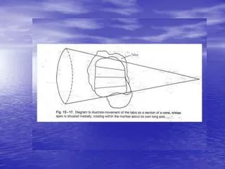
Device for Collecting Stress Images of Subtalar Joint. Patrick Melton Daniel Escobar 3 /15/11. Hindfoot Anatomy. Introduction.

E N D
Device for Collecting Stress Images of Subtalar Joint Patrick Melton Daniel Escobar 3/15/11
Introduction • Subtalar joint analysis is often overlooked in most chronic lateral ankle instabilities. Doctors perform exploratory surgery rather than conducting a complete diagnosis of the subtalar joint. • Currently, most radiographic imaging procedures to analyze the subtalar joint yield inaccurate results and exaggerated instabilities. • With the correct manipulation of the foot, it is anticipated that simple radiographic images can be collected in order to diagnose instabilities of the joint.
Purpose • Create a device that will apply stress to the subtalar joint for the best possible radiographic images to allow for accurate measurements and determine the stability of the joint.
Cobey View Reilingh, M., Beimers, L., Tuijthof, G., Stufkens, S., Maas, M., & van Dijk, C. (2010). Measuring hindfoot alignment radiographically: the long axial view is more reliable than the hindfoot alignment view. Skeletal Radiology, 39(11), 1103-1108.
Long Axial Alignment View • Most reliable and accurate measurements, highest correlation coefficients. • Reilingh, M., Beimers, L., Tuijthof, G., Stufkens, S., Maas, M., & van Dijk, C. (2010). Measuring hindfoot alignment radiographically: the long axial view is more reliable than the hindfoot alignment view. Skeletal Radiology, 39(11), 1103-1108.
Design Considerations • Design allows for inversion of the calcaneus for hindfoot assessment in weight bearing position. Price, Mark. (Designer). (2006). Measuring hindfoot with dynastat. [Web]. Retrieved from http://www.gp-training.net/rheum/gait/gait2.jpg
Design Considerations (Ctd) • Applies non-weight bearing inversion stress. • Allows for analysis of subtalar tilt angle. Brantigan, JW, Pedegana, LR, Lippert, FGInstability of the subtalar joint. Diagnosis by stress tomography in three casesJ Bone Joint Surg Am 1977 59: 321-324
Design History – Secondary Model • Added second plate in the front to allow for twisting motion. • Added sliding heelcup and shortened space in between forefoot plate and base plate.
Design History – Third Model • Added rack and pinion lifting mechanism. • Increased distance between forefoot plate and base plate. • Allows for more support and adjustability but method to lock it in place is unknown.
Design Roadblocks • Main challenge is to create a locking mechanism that is adjustable, simple to use, and can support up to 500 lbs. • Currently there are three concepts in consideration: • Rack and Pinion– Pros: Adjustable, easy to use, weight is more distributed. Cons: locking mechanism unknown. • Worm gear– Pros: Adjustable, lockable. Cons: Creates a larger moment, need to examine in more detail. • Threaded bolt– Pros: Adjustable, easy to use, lockable. Cons: Must be able to support entire load.
Materials Selection • Most of the device will be made from a radiolucent plastic called Delrin, manufactured by DuPont. • Tensile strength – 400 ksi • Yield Strength – 10 ksi • Density – 1.42 g/cm3 • Used for gears, springs, chains, screws, nuts, insulation.
Cost Consideration • Delrin sheet - 12” x 24” x 1”, costs approximately $150 each. • Delrin rod - 1’ in length, ½” diameter costs $1.39 per foot. • Wooden scaled prototype approximately $100 max. • Manufacturing will be done in-house. • Total cost will not exceed $500.