Innovative Device for Enhanced Subtalar Joint Visualization and Stability Assessment
100 likes | 253 Vues
This report outlines the objective of designing a device that optimizes ankle positioning for better visualization of the subtalar joint and improved stability analysis. Various radiographic views, including Cobey and Stress Broden, are examined, revealing limitations of the Stress Broden view in accurately assessing subtalar joint status. Challenges such as effective stress application and accurate simulation of the subtalar joint using a kinematic model are addressed. The device design includes adjustable heel cups and plates for comprehensive foot positioning, enhancing the analysis of the subtalar joint dynamics.

Innovative Device for Enhanced Subtalar Joint Visualization and Stability Assessment
E N D
Presentation Transcript
Stress Application Device for the Subtalar Joint Status Report 1 Patrick Melton Daniel Escobar
Recap - Objective • The objective is to utilize the research of the medical literature gathered and translate the findings to design a device that will position the ankle for improved visualization of the subtalar joint and allow for enhanced stability analysis.
Recap – Radiographic Views • Cobey view • Hindfoot Alignment view • Long axial view • Stress Broden view
Update – Stress Broden View • Two articles concluded that the Stress Broden view is not ideal for subtalar joint analysis. • Compared subtalar tilt in unstable and normal ankles using Stress Broden view vs. CT scan – measurements were not statistically significant. • Stress Broden view recorded high degree of subtalar tilt in both normal ankles and unstable ankles – accurate measurements could not be obtained.
Roadblocks • How does the subtalar joint act under different areas of stress application? • What is the best way to open the subtalar joint by applying stress to the ankle for an ideal radiographic view?
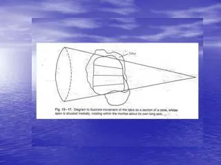
Possible Solution • Obtain kinematic model of the hindfoot so that we can simulate the application of stress on the subtalar joint. • Forefoot is not included, so it will be difficult to accurately simulate our device using the kinematic model.
Possible Solution • Article used a combination of supination and dorsiflexion. Ishii, T., S. Miyagawa, et al. (1996). "SUBTALAR STRESS RADIOGRAPHY USING FORCED DORSIFLEXION AND SUPINATION." J Bone Joint Surg Br 78-B(1): 56-60.
Update - Design • Should have different size heel cups, or a single adjustable heel cup. • Three layers: Base plate, full foot plate, forefoot plate. • Base plate: foundation for adjustable locking mechanism and heelcup. • Full foot plate: allows for angular adjustment of entire foot, enabling supination. • Forefoot plate: will allow for additional adjustment of forefoot, enabling dorsiflexion.