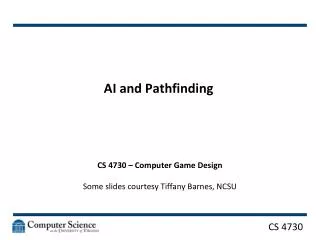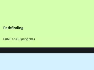
PathFinding Methodology for Interposer and 3D Die Stacking
PathFinding Methodology for Interposer and 3D Die Stacking. Sherry Xiaoxia Wu*, Ravi Varadarajan † , Navneet Mohindru † , Durodami Lisk*, Riko Radojcic* *Qualcomm Inc. † Atrenta Inc. Outline. Motivation of PathFinding Methodology PathFinding Methodology Flow Demonstrations using an Example

PathFinding Methodology for Interposer and 3D Die Stacking
E N D
Presentation Transcript
PathFinding Methodology for Interposer and 3D Die Stacking Sherry Xiaoxia Wu*, Ravi Varadarajan†, Navneet Mohindru†, Durodami Lisk*, Riko Radojcic* *Qualcomm Inc. †Atrenta Inc.
Outline • Motivation of PathFinding Methodology • PathFinding Methodology Flow • Demonstrations using an Example • Conclusion
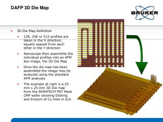
Typical 3D Design Options Courtesy: Si2
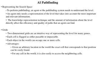
Motivation of PathFinding Methodology • Navigating many choices …. • Cost, power, performance… • Co-optimize process & design • Need a structured design exploration methodology • Past experience not applicable to disruptive technologies • Not tie to legacy design • Quick and flexible • High fidelity/low accuracy Need methodology to make the selections PathFinding
PathFinding Methodology Many more challenges in 3D: - IP/tier assignment - Intra/inter die floorplan - Power & thermal - Timing across dies - TSV & stack configuration - TSV/bump alignment Design Architecture RTL, Blackbox, Netlist, Top level SDC/DEF/IO Constr, Interfaces, Tier/die config. Early Design Planning Physical Units Handoff 1 Logical, Physical, Timing Physical Units Handoff N Logical, Physical, Timing … Tier/ Die 1 Tier/ Die N … Backend Implementation 1 Backend Implementation N
PathFinding Methodology Create logical partitions for each die 3D stack XML file Modify partitions Are interconnectivity and TSV reports for all dies acceptable? N Y Commit logical partitions in to 3D physical partitions Physical prototyping on each die partition Modify TSV cluster/locations Are all dies physically feasible? N Y Backside RDL/ Interposer routing Modify number of RDL layers/bump locations Is Backside RDL routing/Interposer feasible? N Y • Handoff 3D stack XML file with partitions • Handoff DEF file for every partition
3D Format - XML • XML: Ongoing Standardization • Interposer and 3D die stacking Two Dies on a Passive Interposer Two Stacked Dies
Logic Partition Top die frontside net Bottom die front-side net Top die frontside ubump Bottom die backside net Bottom die backside ubump Dummy net TSV Block in top die Block in bottom die
Floorplan Constraints and An Example TSV/ubmp size, XML Create/mark TSV/ubump clusters Assign TSVs/ubump to clusters Set cluster utilization/aspect ratio FP constraints: guide/region • Floorplan constraints • Blackbox locations • Die utilization: block area/die area • Number of TSV clusters: 2, 4, 8 • TSV size/pitch/location • ubump size/pitch/location
Floorplan Options for a LoL Case • 2 TSV clusters • 4 TSV clusters • 8 TSV clusters • TSV cluster guide • TSV aspect ratio • Number of TSV clusters • TSV cluster guide • TSV cluster aspect ratio • TSV pitch TSV
Frontside Routing Analysis • Vary bottom and top routing layer • Vary macro routing layer • Vary routing porosity in a window for PDN/DFT consideration
Backside Routing Analysis • Explore BRDL options when TSV and ubumps are not aligned • Vary number of BRDL layers and pitch Foundry OSAT Above 2 BRDL layers, more complicated and expensive process ubump group 2
2.5D Interposer • Interposer Floorplan, Interposer Routing and Congestion 2 interposer routing layers, pitch = 1um 2 interposer routing layers, pitch = 5um 2 interposer routing layers, pitch = 2um
Conclusion • A physical PathFinding methodology for interposer and 3D die stacking is presented • The results show that with this methodology, users are able to explore different process and design options for early estimation of their designs to reduce expensive backend iterations • This methodology is a general flow, it also works for mixed interposer and 3D die stacking