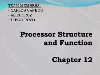
Chapter 12 CPU Structure and Function
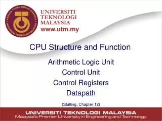
Chapter 12 CPU Structure and Function. CPU Structure. CPU must: Fetch instructions Interpret instructions Fetch data Process data Write data Major components of CPU ALU Control unit Register. 2. CPU With Systems Bus. 3. CPU Internal Structure. 4. Registers.

Chapter 12 CPU Structure and Function
E N D
Presentation Transcript
Chapter 12 CPU Structure and Function
CPU Structure • CPU must: • Fetch instructions • Interpret instructions • Fetch data • Process data • Write data • Major components of CPU • ALU • Control unit • Register 2
Registers • CPU must have some working space (temporary storage), which called registers • Number and function vary between processor designs • One of the major design decisions • Top level of memory hierarchy • Small set of high speed storage 5
Registers • Two types of registers • User visible registers: • may be referenced by assembly-level instruction • Control and status: • used by control unit to control CPU operations and by OS programs 6
User Visible Registers • General Purpose • Data • Address • Condition Codes 7
General Purpose Registers (1) • May be used for true general purpose • E.g., PDP-11: R0 ~ R7 • May be used for restricted purpose • E.g., stack pointer, floating point registers • May be used for data or addressing • Data • Accumulator, Motorola 68000: D0 ~ D7 • Addressing • Segment , stack pointer, Motorola 68000: A0 ~ A7 8
General Purpose Registers (2) • General purpose vs. Special purpose • Make them general purpose • Increase flexibility and programmer options • Increase instruction size & complexity • Make them specialized • Smaller (faster) instructions • Less flexibility • Which is better? • No final and best answer • Trend toward specialized 9
General Purpose Registers (3) • How many? • Between 8 ~ 32 • Fewer then, more memory references • Also, more registers do not noticeably reduce memory references • However, a new approach, which finds advantage in the use of hundred of registers, is exhibited in some RISC ! 10
General Purpose Registers (4) • How big ? • Large enough to hold full address • Large enough to hold full word • Often possible to combine two data registers • That is, two registers to hold one long integer • In C programming • long int a; // 64 bits 11
Control & Status Registers • Program Counter • Instruction Decoding Register • Memory Address Register • Memory Buffer Register • Program Status Word (PSW) 12
Program Status Word • A set of bits • Includes Condition Codes (CCR) • Sign of last result • Zero • Carry • Equal • Overflow • Interrupt enable/disable, interrupt mask • Supervisor 13
Program Status Word - Example • Motorola 68000’s PSW 14
Supervisor Mode • Intel ring zero • Kernel mode • Allows privileged instructions to execute • E.g., system call • Used by operating system • Not available to user programs 15
Condition Code Registers (CCR) • Sets of individual bits • Set by CPU as the result of operation • e.g. result of last operation was zero, Z bit is to be ‘1’ • Can be read (implicitly) by programs • e.g. Jump if zero • Can not (usually) be set by programs • Some instructions can set or clear the condition registers 16
Condition Code Registers (CCR) • Condition Code Register Bits N, Z, V, C • N (negative) bit is set if result of operation in negative (MSB = 1) • Z (zero) bit is set if result of operation is zero (All bits = 0) • V (overflow) bit is set if operation produced an overflow • C (carry) bit is set if operation produced a carry (borrow on subtraction) • in MC68HC11E9, CCR is… • 8-bit register contains five condition code indicators (C,V,Z,N and H), two interrupt masking bits, (IRQ and XIRQ) and a stop disable bit (S) • automatically updated by most instructions. H: Half carry flag 17
Other Registers • May have registers pointing to: • Process control blocks • Interrupt vectors • Page table pointer • CPU design and operating system design are closely linked 18
Instruction Cycle • Review 20
Indirect Cycle • May require memory access to fetch operands • Indirect addressing requires more memory accesses • Can be thought of as additional instruction subcycle 21
Data Flow (Instruction Fetch) • Depends on CPU design • In general: • Fetch • PC contains address of next instruction • Address moved to MAR • Address placed on address bus • Control unit requests memory read • Result placed on data bus, copied to MBR, then to IR • Meanwhile PC incremented by 1 24
Data Flow (Fetch Diagram) 2 3 1 6 4 5 25
Data Flow (Data Fetch) • IR is examined • If indirect addressing, indirect cycle is performed • Right most N bits of MBR transferred to MAR • Control unit requests memory read • Result (address of operand) moved to MBR • The address of operand moved to MAR again! • Control unit request memory read • Result (data operand) moved to MBR Instruction set Op code 0x11 memory Instruction set format 0x11 0xFF operand op code 0xFF ‘A’ N bits 26
Data Flow (Indirect Diagram) 2 1 3 27
Data Flow (Execute) • May take many forms • Depends on instruction being executed • May include • Memory read/write • Input/Output • Register transfers • ALU operations 28
Data Flow (Interrupt) • Simple, predictable • Current PC saved to allow resumption after interrupt • Include 1. Contents of PC copied to MBR 2. Special memory location (e.g. stack pointer) loaded to MAR 3. Control unit: WRITE 4. MBR written to memory 5. PC loaded with address of interrupt handling routine (Next instruction (first of interrupt handler) can then be fetched) 29
Data Flow (Interrupt Diagram) 2 5 3 1 4 30
Prefetch • Fetch accessing main memory • Execution usually does not access main memory • Can fetch next instruction during execution of current instruction • Called instruction prefetch 31
Improved Performance • But not doubled: • Fetch usually shorter than execution • Prefetch more than one instruction? • Any jump or branch means that prefetched instructions are not the required instructions • Add more stages to improve performance 32
Pipelining • Fetch instruction • Decode instruction • Calculate operands (i.e. EAs) • Fetch operands • Execute instructions • Write result • Overlap these operations 33
What is Pipelining ? is a technique to increase their throughput (the number of instructions that can be executed in a unit of time) 34
The Concept of Pipelining The case of washing clothes Tasks Ann, Brian, Cathy and Dave each have one load of clothes to wash, dry and fold Washing takes 30 mins Drying takes 40 mins Folding takes 20 mins Washing, Drying and Folding Output: clean clothes Input : dirty clothes 35 Ref) http://www.seas.upenn.edu/~palsetia
Case 1: Sequential Laundry Task order : Ann, Brian, Cathy and Dave Entire workload takes 6 hours to complete 36
Case 2: Pipelined Laundry Pipelined laundry takes only 3.5 hours Speedup = 6 hours / 3.5 hours = 1.7 Pipelining did not reduce the completion time for one task but it helps the throughput of the entire workload 37
Two Stage Instruction Pipeline (more) • To fetch an instruction, accessing main memory is required • Execution usually does not access main memory • So it can fetch next instruction during execution of current instruction • It is called instruction prefetch or fetch overlap • Ideally instruction cycle time would be halved (if durationF = durationE …) 39
Two Stage Instruction Pipeline (more) • But in reality, it is not doubled because… • The execution time is longer than the fetch time • The conditional branch instruction makes the address of the next instruction to be fetched unknown 40
Two Stage Instruction Pipeline (more) • Add more stages to improve performance • Reduce time loss due to branching by guessing • If not branched use the prefetched instruction • else discard the prefetched instruction fetch new instruction 41
The Six Stage Pipelining • More stages more speedup FI: Fetch instruction DI: Decode instruction CO: Calculate operands (i.e. EAs) FO: Fetch operands EI: Execute instructions WO: Write result • Various stages are of nearly equal duration • Overlap these operations 42
Timing Diagram for Instruction Pipeline Operation • = pipeline cycle time k = number of stages : 6 n = number of instructions : 9 • To execute 9 instructions in 6 stage-pipeline device, it takes 14 time units to complete • cf. in the case of no pipeline: 54 time units are required 43
Speedup of Pipelining • Parameters • = pipeline cycle time = time to advance a set of instructions one stage • k = number of stages • n = number of instructions • Time to execute n instructions (In the case of no branch) Tk = [k + (n - 1)] • Time to execute n instructions without pipelining T1 = nk 44
Speedup of Pipelining • Speedup of k-stage pipelining compared to w/o pipelining 45
Limitation by Branching Conditional branch instructions can invalidate several instruction prefetches For example, Instruction 3 is a conditional branch to instruction 15 Next instruction’s address won’t be known till instruction 3 is executed (at time unit 7) pipeline must be cleared No instruction is finished from time units 9 to 12 performance penalty 46
The Effect of a Conditional Branch on Instruction Pipeline Operation * * * * 47