Download
1 / 21
220 likes | 454 Vues
Pulsar II Hardware Overview Jamieson Olsen, Fermilab 14 April 2014. Outline. ATCA Overview Pulsar II Hardware Front Board Rear Transition Module Mezzanine Data Transfer Options Pulsar IIa Prototype Results Conclusion. ATCA Overview. Mature telecom standard IPMI Protocol

E N D
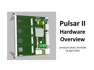
Pulsar IIHardwareOverviewJamieson Olsen, Fermilab14 April 2014
Outline • ATCA Overview • Pulsar II Hardware • Front Board • Rear Transition Module • Mezzanine • Data Transfer Options • Pulsar IIa Prototype Results • Conclusion Pulsar II Hardware Overview / J.Olsen
ATCA Overview • Mature telecom standard • IPMI Protocol • Hot swap, redundant modules • Fully instrumented • High power: 300-450W per slot • Front to back airflow • Option for vertical airflow • Boards measure 8U x 280mm • User defined Zone-3 for RTM I/O • 2 to 14 slots per shelf • Full mesh backplane option • 40 Gbps per channel (>7 Tbps) • 100 Gbps per channel coming soon ASIS ATCA shelf at Fermilab. This is a 40G full mesh backplane rated for 450W per slot. Pulsar II Hardware Overview / J.Olsen
Pulsar IIb Front Board • Xilinx Virtex 7 FPGA • XC7VX415T – XC7VX690T • Up to 80 GTH transceivers • 40 for RTM • 28 for Fabric • 12 for Mezzanines • Four FMC Mezzanines • 35W each • LVDS + SERDES up to 60 Gbps • Compatible with LAPP IPMC module • 10/100/1000 Base Interface Port • Backplane clock distribution Pulsar II Hardware Overview / J.Olsen
Block Diagram RTM Optical Transceivers Full Mesh Fabric Interface Dual 48VDC and platform Management (IPMI) Pulsar II Hardware Overview / J.Olsen
Programming the FPGA • JTAG bus driven by the IPMC • Mux to automatically select the Xilinx programmer cable • FPGA also has SPI flash attached • “Indirect” Flash programming • Time to program? • XC7V690T = ~100 Mbits Pulsar II Hardware Overview / J.Olsen
IPMC Module (LAPP) • Dual ARM microcontrollers • IPMI, I2C sensors, AMC/RTM, LEDs, etc. • General User I/O, JTAG, 100BASE-T Ethernet Pulsar II Hardware Overview / J.Olsen
Pulsar IIb Power Distribution 48VDC Yellow = LDO Linears Orange = Switchers, GE/Lineage DLYNX with PMBus Interface Pulsar II Hardware Overview / J.Olsen
Rear Transition Module • Fiber optic transceivers • 8 QSFP+ • 6 SFP+ • Up to 380 Gbps • Intelligent FRU • µC monitors optical modules • Hot Swap • PICMG 3.8 “Zone-3A” compliant Pulsar II Hardware Overview / J.Olsen
Test Mezzanine Card • Kintex XC7K160T FPGA • 4 SFP+ Transceivers • 6.6 Gbps GTX • 128MB DDR3 • Socket for testing ASICs • FPGA Mezzanine Card (FMC) connector is compatible with FPGA development boards • 74 mm x 149 mm Pulsar II Hardware Overview / J.Olsen
System Integration • All ATCA platforms support a dual star Base Interface network • 10/100/1000BASE-T Ethernet • Used for slow controls, downloading firmware, etc. • COTS “switch blades” support separate networks on the Base and Fabric Interfaces • Pulsar IIb supports up to 40G Ethernet Fabric connections to the switch • We are testing the IPBus firmware now • At Fermilab we are using the Emerson F125 switch (10G Ethernet) Pulsar II Hardware Overview / J.Olsen
Data Sharing • The full mesh backplane is a natural fit for triggers where hits are shared across tower boundaries • Particularly true if data sharing is irregular • Effectively blurs the distinction between FPGAs • First Application: FTK Data Formatter • 16 φ x 4 η towers • 32 boards in 4 crates http://www.youtube.com/watch?v=wgDbm_izOXk Pulsar II Hardware Overview / J.Olsen
Time Multiplexed Transfers • The full mesh backplane is also useful in systems which consist of many parallel processing engines • In this example • 10 input boards • 40 Processor Mezzanines • 1 “Gateway” board • 1 output board Pulsar II Hardware Overview / J.Olsen
Multipath Transfers • If the firmware supports packet retransmission then there are many ways to get from A to B • Effective use of under-utilized backplane channels • Must account for additional latency, however. • Currently we are simulating firmware to support “route through” packet handling. Pulsar II Hardware Overview / J.Olsen
Pulsar IIa Prototype • Designed and tested in 2013 • Dual Kintex K325T FPGAs • 10 Gbps GTX Transceivers • Many Unknowns: • First ATCA board design • First FMC mezzanine design • First Xilinx 7-Series FPGA design • First high speed design using high performance PCB materials Pulsar II Hardware Overview / J.Olsen
Pulsar IIa Bench Testing • A single slot “Mini Backplane” was developed at Fermilab • Provides power, a base interface RJ45 port, and loopback for all backplane channels • IPMC microcontroller software was created to support Telnet and FTP access • Download firmware images to SDHC flash memory card • Board control via command line • FPGA local bus is working well at 10 Gbps • Backplane and RTM loopback tests are working well at 6.25 Gbps • 10 Gbps operation is possible, but requires fine tuning GTX settings 6.25 Gbps 10 Gbps Pulsar II Hardware Overview / J.Olsen
Pulsar IIa Crate Testing • Our first ATCA shelf is 10G • 4 x 2.5 Gbps • ELMA rated for ~4 Gbps • Our crate level testing has demonstrated BER of 4.2E-17 @ 6.5 Gbps • No apparent degradation across length of backplane • Tested communication with F101 and F125 switch blades • Recently we acquired an ASIS 40G shelf and tests are ongoing Seven Pulsar IIa boards installed in our ELMA 10G ATCA shelf at Fermilab Pulsar II Hardware Overview / J.Olsen
Pulsar IIb Layout • Incorporate everything we learned from designing and testing the Pulsar IIa • The goal is to have large receiver margins and wide open eyes at 10 Gbps and beyond • Keep high speed traces direct and clean (“less is more” philosophy) • Compensate for every connector, via, and discrete component in the signal path • At 10 Gbps signal transitions are 10-20ps, so every layer transition and stub matters! • Work closely with the PCB manufacturer to develop a stackup and trace geometry that meets performance requirements and can be manufactured! • 14 Layers • Nelco N4000-13 EP SI materials Pulsar II Hardware Overview / J.Olsen
Conclusion • The ATCA platform is a natural fit for many HEP applications • Excellent bandwidth, power, and telecom reliability • Many interesting data transfer options • Our first ATCA prototype board works quite well • GTX transceivers are solid at 6.25 Gbps, some tuning needed to get to 10 Gbps • The Pulsar IIb prototype boards are being fabricated now Pulsar II Hardware Overview / J.Olsen
Backup Slides Pulsar II Hardware Overview / J.Olsen
Pulsar IIb FPGA Power Pulsar II Hardware Overview / J.Olsen