Precision Measurement of Positive Muon Lifetime
Collaborative research for the accurate determination of the positive muon lifetime using a specialized detection system and systematic error control methods. Seeking collaborators to enhance surface muon beam expertise.

Precision Measurement of Positive Muon Lifetime
E N D
Presentation Transcript
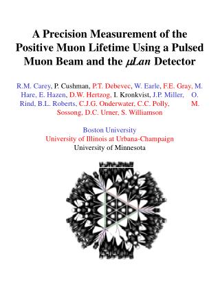
A Precision Measurement of the Positive Muon Lifetime Using a Pulsed Muon Beam and the mLan DetectorR.M. Carey, P. Cushman, P.T. Debevec, W. Earle, F.E. Gray,M. Hare, E. Hazen, D.W. Hertzog, I. Kronkvist, J.P. Miller, O. Rind, B.L. Roberts,C.J.G. Onderwater, C.C. Polly, M. Sossong, D.C. Urner, S. WilliamsonBoston UniversityUniversity of Illinois at Urbana-ChampaignUniversity of Minnesota
Collaboration • Subset of Muon (g-2) Experiment at BNL • Responsibilities there include: • electromagnetic calorimeters • traceback wire chambers • waveform digitizers • multi-channel TDCs • flight simulator • custom PMT bases • laser and LED calibration systems • GEANT (and other) simulations • systematic error evaluations • data acquisition • data analysis • (we did not contribute significantly to the magnet design, or field monitoring tasks) • We are actively seeking additional collaborators for mLan, especially in the area of surface muon beam issues, mSR, and local PSI expertise
Proposal Summary • Determine GF to better than 1 ppm by measuring tm • 1012 good events • “Pulsed” low-energy muon source • Symmetric, segmented timing detector • “Clocks” • Main focus: Systematic Error Control • pileup • gain changes “early-to-late” • backgrounds • errant muons • stray positrons • … • Running Plan • many “tests” to establish key systematic error benchmarks • relatively short data collection period... • … which can be repeated, if needed...
Classic Lifetime Techniques • “1 at a time” • Each muon (or pion) enters target individually with pre- and post-quiet periods. Watch for decay positron and record its time. • Must know incoming efficiency and pileup well • For 1012, need about 4 x 10⁷ sec … several years ! • “Multiple Experiments at Once” “m” beam by time… mLan muons arrive “at once”, decay into segmented detector by space… FAST pions arrive “DC” into highly segmented timer/tracker
“Radioactive” Mode • Burst of N muons arrives during accumulation period Tacc • Observe muon decays during measuring period of length Tmeas • No other muons arrive during this time • Get another burst • Ideally: • Nsmall; reduces pileup • Tacc +Tmeas ~ 20 msec; cycles fast • At PSI with kicker like MORE setup, • cycle frequency ~ 50 kHz • N ~ 10 - 15 works very well • Compare with proposed RAL approach • cycle frequency ~ 50 Hz (1000 times slower) • N ~ 2,000 or more and very long run
Generic Proposed Setup at PSI quads quads Kicker Plates separator • After separator, expect e+/m+ at few % • Kicker sends beam left or right • 1.5 x 10⁷ beam implies around 15 muons per 1 ms accumulation period … and 12 at the start of the measuring period. +10 kV 0 -10 kV Kicker HV Supply Desired Extinction 99.9% 20 ms Update: Better cycle per PSI kicker HV supply and expt. measuring period
Beam into Detector e+ • Option 1 Helium Bag 1 mm Sulfur disk or other target, (e.g., iron oxide) thin Aluminized mylar wall pmt Desired Efficiency 99.9% • Option 2 e+ Helium Bag Active 1 mm thick fiber veto for errant muons pmt
Muon Scattering in Scintillator and Window Scintillator 0.2 mm Window 0.15 mm
Tests of muons into target • Extinction fraction • easily measured to high accuracy • critical to obtain its time dependence • Beam counter efficiency • special test with 2nd small counter behind Note: only time-dependence in these quantities can hurt us • Beam distribution on target • use existing thin straw chamber to establish profile • Outscattered, errant muons • instrument helium bag to establish this; • also can put in ring around area for permament magnet setup to count number of muons hitting this device
counts time Detector and “Clock” must be designed from systematic error issue consideration • Question: What can go wrong? • Any “early-to-late” changes in detection capability • time shifts • gain or threshold shifts • Effective change due to residual polarization of muons • target choice • external B field • Pileup • Backgrounds threshold Ee countsi time
counts time Pileup: When 2 particles are counted as 1* • Time-dependent; rate squared • pileup fraction ~ e-2t/t • To reduce: • Segment Detector Fseg = 180 • Double-hit timing resolution dt = 10 ns • Overlap rejection by energy Fdh = 10 • At this level we can EASILY correct for it since we will know the factors above very well (our values) *Note: if 1 is counted as 2, only changes c2 (if probability is time independent)
Segmentation • 180 coincident timing tiles • 3D symmetric • additional point-symmetry with respect to target for tile pairs • Icosahedral geometry: 20 sides • Each “SuperTriangle” contains 9 identical tiles mLan Detector SuperTriangle Target inside Beam enters Tile segment
Tile Elements • Inner: 6.4 mm thick 300 pe/mip • Outer: 3.2 mm thick 160 pe/mip Note: no real gap between tiles e+ outer inner Note: actual prototypes, have smoothly tapered cone with round top, etc.
dt resolution • Fast scintillator: e.g. BC418 • Fast PMTs: e.g. R6427 • Two time measurements per positron • 500 MHz waveform digitizer sampling of pulses • Based on our (g-2) experience … can resolve 10 ns with UNequal pulses, and 400 MHz sampling • We are actually hoping to push this number down a bit. 10 ns is not overly optimistic A “similar” MIP pulse in a (g-2) counter with BC404, tube as described, and custom base. RED pulse is a copy displaced by 10 ns
Fdh Rejection* • Normal mode: • single e+ passes through both scintillator tiles leaving “mip” type monoenergetic signal • Two with dt < 10 ns • “double” mip signal in both • Question: How does this look compared to Landau tails ? • cut in 2-dimensional space • obtain a factor Fdh up to 200 ! • We are ONLY using Fdh of 10 in our calculations to be very conservative *dh = double hit
Pulse-height and timing data • For (g-2), we have developed timing based on • discriminator/derandomizer/TDCs and • waveform digitizers (WFD) • Overwhelming feeling: Only the WFDs matter. • Additionally, they provide the pulse height used for the Fdh rejection algorithm WFD 500 MHz We plan to use 1 WFD per tile and separate the signals by time. When either fires, the WFD records what is going on in the other….reduces threshold worries
Spin Precession Effectschange in effective efficiency versus time • Asymmetry in detector • mimimized by point-like symmetry • 90 tile pairs for (F-B)/(F+B) tests • Residual polarization of individual stopped muon • target choice • depolarization high • Residual ensemble-averaged polarization after accumulation period • dephasing Tacc by precessing by fast spin relaxation time
“pause” for spin relaxation Target Choice • Sulfur depolarizes muon spin to about 3% during stopping. • (studies ongoing at PSI now) • Good conductors preserve polarization • used for tests of detector symmetry • Other targets feature strong B fields, randomly aligned • This reduces <P> = 1/3. • e.g., iron oxide • If dynamic changes (fluctuations of field orientations), <P> smaller • e.g., certain spin glasses
Dephasing • A75 G transverse field, rotates m in 1 ms • Incorporate this small field around target to dephase muons • The factor k multiplies the individual residual polarization to yield the net ensemble-averaged polarization k < 0.1 0.05
Overall effect Single m, Single tile, No depolarization Add tile pair; asymmetry in pair 2% Add depolarization to 3% (sulfur) Add dephasing factor k = 0.1 • Steps to eliminating systematic error due to spin orientation and precession 1 ppm error 75 G field
Proof of factors • Step 1: Detector tile symmetry, h • Use Al or Ag which preserves polarization in a 1 at a time mode; no B field • Measure (F-B)i versus time for all tile pairs • Adjust alignment if needed • Step 2: Test of Depolarizing targets • Insert Sulfur or other candidate targets and measure mSR signal in a transverse field. What is the residual <P> ? • NOTE: We hope to make use of existing, expert mSR facility and collaborators to do this step early, in year 1 • Step 3: Determine Dephasing factor • Al or Ag target • B field at 75 G transverse • Chopped beam, 1 ms accumulation period. • Measure residual polarization in single tile • Measure residual polarization in tile combination
Gain (threshold) Stability • Threshold ~ 2-3 MeV ( thin counters) • (upper 99% of electron energy spectrum) • Gain stability to 1% (not hard) • largely determined by number of photoelectrons • For Npe > 47, no problem. • Prototypes have Npe > 160
Backgrounds • Flat (no problem with long measuring period to establish level) • cosmics • accelerator-related room background • must establish that there is no time correlation with chopping • Rare Decays • May cause “double” hit for one time. • No problem because probability is stable, early to late • Only effects the overall c2 in a predictable way 1.4% 0.0034%
Electronics & DAQ • Main development, 500 MHz waveform digitizer • for us, 2nd generation…having built the 400 MHz system for (g-2) (see layout) • Basic Idea related to readout… • use FIFO memory in order to readout as you go • Each event consists of approximately 40 WFD samples + timewords • Reduce this number to simpler list using online processor • NORMAL EVENT • Spill # • Tile # • Time Inner • Energy Inner • Time Outer • Energy Outer • AbNormal EVENT + 10% of all others • Spill # • Tile # • WFD Records to tape to tape
DAQ continued • Data Volume (an idea only) • 1012 events (a lot!) • normal events(13.5 Tb) • 12 bytes/event 9 events per spill • decay positron • 15 bytes per spill • relative times of incoming muons • abnormal and 10% events (6 Tb) • 60 bytes/event additionally • overall: • ~ 20 Tb per 1 ppm measurement
Beamtime and Run Plans • Year 1 • Build prototype SuperTriangles • Tube and Base selection • Establish funding for full detector • Use mSR setup to establish target depolarization properties • 1 week plus collaboration with experts • Tests of 2 SuperTriangles system with modest DC surface m beam (no chopper, low intensity) • light output • asymmetry • cross talk • etc. • 1 week plus setup of 1-2 weeks
Beamtime and Run Plans • Year 2 • Build mLan detector at home institutes • Build mechanical carriage • Build WFDs • Develop DAQ system and begin purchases or components • At PSI • Test of half or more of full system to debug system issues • Use DC beam (no chopper yet unless it is ready) • Tests of detector uniformities • Development of software energy/time algorithms for online CPUs • Make a 10 ppm measurement of tm • 4 weeks beam plus setup 2 weeks
Beamtime and Run Plans • Year 3 • Calibration system finalization • Complete electronics • Complete DAQ • Complete chopper and beamline installation modifications • At PSI • Test beamline and chopping • 2 weeks of beamtime for tuning and establishing parameters • Debug full system • 1 week for tests and debugging • Make a 1 ppm measurement of tm with target #1 • 6 weeks beam • Year 4 (if necessary) • Make a 1 ppm measurement of tm with target #2 • 6 weeks beam + 2 weeks setup again
CONCLUSION • A new measurement of the muon lifetime (and hence GF) is necessary to reap the full benefit of precision measurements at present and future accelerators and recent theoretical progress. • A chopped beam time-structure available at PSI should make it possible to improve the measurement of GF by a factor of 10-20, in a modest amount of time. • Our collaboration is capable of carrying out this task. While questions remain, we believe the basic experimental concept is sound. It is also complementary to other proposed approaches. • Our basic request to PSI is to help to establish the beam and chopping device. • The MORE scheme looks appropriate with modest changes • We are very hopeful to have enticed local experts to collaborate!!