Download
1 / 35
350 likes | 467 Vues
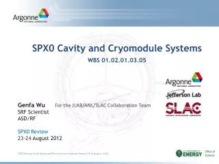
SPX0 Cavity and Cryomodule Systems WBS 01.02.01.03.05. Genfa Wu SRF Scientist ASD/RF SPX0 Review 23-24 August 2012. For the JLAB/ANL/SLAC Collaboration T eam. Outline. WBS Scope of this system Requirements Design Interfaces Risks considered (Fault Analysis) Summary.

E N D
SPX0 Cavity and Cryomodule SystemsWBS 01.02.01.03.05 Genfa Wu SRF Scientist ASD/RF SPX0 Review23-24 August 2012 For the JLAB/ANL/SLAC Collaboration Team SPX0 Review of the Advanced Photon Source Upgrade Project 23-24 August 2012
Outline • WBS Scope of this system • Requirements • Design • Interfaces • Risks considered (Fault Analysis) • Summary SPX0 Review of the Advanced Photon Source Upgrade Project 23-24 August 2012
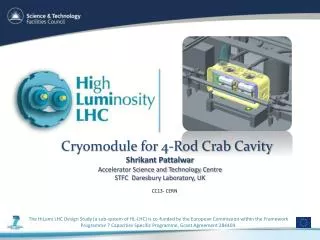
Cavity and Cryomodule System Scope • Fabricate and test major cavity system components. • Fabricate, test and install a single cryomodule containing two SRF deflecting cavities (MARK II) with LOM/HOM waveguide dampers and tuners in Sector 5 of the APS storage ring. SPX0 Review of the Advanced Photon Source Upgrade Project 23-24 August 2012
Cavity and Cryomodule System Requirements • Discuss requirements, PRD, ESD as exist. • What KPP’s are supported (if applicable) • Discuss the technical goals / science (if appropriate) SPX0 Review of the Advanced Photon Source Upgrade Project 23-24 August 2012
SPX0 Physics • To demonstrate operation of two fully-powered independently-controlled superconducting deflecting cavities with beam, including quantitative measurements of their impact on the beam. This test will require low-level rf control, high-power rf, interlock systems, timing and synchronization systems, cavity alignment, beam diagnostics, controls, and beam feedback. • To demonstrate synchronization of a beamline laser with the deflecting cavities at the sub-ps level. When operated in phase, the two cavities will increase vertical beam size everywhere around the ring, and therefore in this configuration will not be compatible with normal user operation. The tests will only be conducted during storage ring beam study periods. When operated in opposite phases with zero net deflecting voltage, no significant effect on the beam is expected, so that the cavities could be operated and tested during user operations. However, this mode of operation will need to be confirmed as acceptable for the user operations first. SPX0 Physics Requirement Document SPX0 Review of the Advanced Photon Source Upgrade Project 23-24 August 2012
SPX0 Main Parameters SPX0 Physics Requirement Document SPX0 Cryomodule Engineering Specification Document SPX0 Review of the Advanced Photon Source Upgrade Project 23-24 August 2012
Cryomodule Engineering Specification*(1) • Cavity nominal operating deflecting voltage 0.5 MV with Q0 ≥ 1e9 • Cavity Qext = 1e6, RF source 5 kW • Cavity Tuner: 2815.486 MHz ±200kHz, resolution < 40Hz • Cavity alignment: • X : ±0.5 mm, Y: ±0.5 mm, Z: ±1.0 mm • Cryomodule alignment: • X : ±0.5 mm, Y : ±0.2 mm, Z : ±1.0 mm • Cryogenic total heatload goal • 2 K heatload< 50 W (+/-5 W) • 80 K heatload < 260 W • Profile needs to fit APS tunnel (Sector 5 envelop) • 73.4” flange to flange • Maximum height from beam line < 40” • Floor to beam < 52.52” *See Engineering Parameters Table for complete details Advanced Photon Source Upgrade (APS-U) project
Cryomodule Engineering Specification* (2) • Bellows • Inter-cavity rigid connection • Warm to cold transition bellows • Unshielded • Longitudinal movement ±0.5 mm, transverse movement ±1.0 mm • Magnetic shielding: ≤ 5 mili-Gauss • Dampers • External LOM load (2 kW) • Internal HOM load ( 500 W, water cooled) • Windows • LOM broad band, 5 kW average power • FPC broad band, 5 kW - 20 kW average power • Interfaces: water, vacuum, RF, instrumentation. *See Engineering Parameters Table for complete details Advanced Photon Source Upgrade (APS-U) project
HOM Damper Deflecting Cavities LOM Damper Specification HOM Damper CCA3 design Input Coupler CCA3 fabrication SPX0 Review of the Advanced Photon Source Upgrade Project, 23-24 August 2012
Deflecting Cavity Performance CCA2 achieved gradient requirement CCB1 is fully satisfied to the spec SPX0 Review of the Advanced Photon Source Upgrade Project, 23-24 August 2012
Impedance Calculations for Single Cavity Vertical Dipole Impedance Monopole Impedance Stability Threshold Stability Threshold Horizontal Dipole Impedance Monopole Stability Threshold Stability Threshold Dipole Stability Threshold Horizontal dipole Vertical dipole Total HOM/LOM power for Mark-II: <0.5/1.8kW for APS 200mA, 24 beam bunch mode SPX0 Review of the Advanced Photon Source Upgrade Project, 23-24 August 2012
Impedance Calculations for Multiple Cavities The propagating modes up to 5 GHz are also damped to meet the desire requirements. There is no trapped mode between the cavities. Liling Xiao et al., Higher Order Modes Damping Analysis for the SPX Deflecting Cavity Cryomodule, IPAC 2012 SPX0 Review of the Advanced Photon Source Upgrade Project, 23-24 August 2012
SPX0 Helium Vessel Design Helium Return Nitronic Rod Mount Tuner Attachment Points Helium Supply SPX0 Review of the Advanced Photon Source Upgrade Project, 23-24 August 2012
Stress Analysis of a Dressed Cavity SPX0 Review of the Advanced Photon Source Upgrade Project, 23-24 August 2012 With the small bellows design, the peak stress in warm CC-A3 cavity dropped to 6,100 psi, which is below the allowable of 6,310 psi. (Conservative to design to peak stress.)
SPX0 Tuner Design SPX Tuner Design Specifications • Tuning Range • +/- 200 kHz • Tuning Resolution • 40 Hz • Rapid Detuning • 3 kHz • < 1msec SPX0 Review of the Advanced Photon Source Upgrade Project, 23-24 August 2012
SPX0 Tuner Design Status: Cavity Measurements • SPX Cavity (CCA3-1) Exercised in Modified C100 Tuner Test Stand • Cavity instrumented with 4 strain gages • Axial Force, Length, and Frequency measured as cavity stretched SPX0 Review of the Advanced Photon Source Upgrade Project, 23-24 August 2012
SPX Tuner Design Status: Cavity Measurements • Modeling Validated SPX0 Review of the Advanced Photon Source Upgrade Project, 23-24 August 2012
Horizontal Test Stand • Horizontal cavity test • 5 kW amplifier • 50 W Cooling @2K • Analog and Digital RF Horizontal test of a dressed cavity is scheduled in October 2012 Advanced Photon Source Upgrade (APS-U) project
ATLAS test area Advanced Photon Source Upgrade (APS-U) project SPX Review, March 3-4 2011 Advanced Photon Source Upgrade (APS-U) project
Cavity Layout for SPX0 Alignment One room temperature shielded beam line bellows each side (not shown) Advanced Photon Source Upgrade (APS-U) project
Bellows adjustment and beam steering ranges Adjustment bounding boxes • Transition bellows allows +/- 0.5mm • Beam line bellows allows +/- 1.0 mm • Beam steering during beam studies allows +/- 0.66mm If a cavity misses beam line by 0.5 mm, adjusting cryomodule alone can bring cavities back to perfect alignment of electric centers. Advanced Photon Source Upgrade (APS-U) project
Alignment Progression 3 2 1 Wire stretch on CMM allows relation of alignment balls to electrical center line of cavity Comparison to pre-HV measurements provide reference Create custom spool piece to link cavities and Use fiducials + wire stretch to confirm that pair electrical center matches combination of pair centers Use alignment balls to transfer fiducialization from beam line to space from on rabbit ears 4 30 um error each time fiducialization transferred Advanced Photon Source Upgrade (APS-U) project Courtesy of Josh Feingold
JLAB Stretched Wire Measurement Advanced Photon Source Upgrade (APS-U) project Slide from Josh Feingold
Low Impedance Unshielded Bellows Loss Factor: 1.517 V/nC Materials: Copper plated Stainless Steel or Phosphor copper alloy Prototype bellows are being fabricated Advanced Photon Source Upgrade (APS-U) project
CLEAN ROOM CAVITY STRING SPX0 Review of the Advanced Photon Source Upgrade Project 23-24 August 2012
COLD MASS SPX0 Review of the Advanced Photon Source Upgrade Project 23-24 August 2012
COLD MASS SPX0 Review of the Advanced Photon Source Upgrade Project 23-24 August 2012
CRYOMODULE ASSEMBLY SPX0 Review of the Advanced Photon Source Upgrade Project 23-24 August 2012
SPX0 Cryogenic Design • SPX0 will use existing CEBAF prototype end cans • No 5K circuit • 5K heat load will be sunk to 2K with heat straps added to stabilize thermal loads as required (waveguides, beamtubes) • Heat exchanger will be external to cryostat • SPX0 will run with liquid dewars and vacuum pumping • Goal - 2 K heat load for the cryostat is 50 watts • The vacuum pump planned for SPX0 has been measured at 64 watts at 23 torr (2.0 K) • If more pumping is needed there is an option to add additional pumping • Helium riser heat flux limit estimated by Gary Cheng • 98 watts at 2.0K, 59 watts at 2.07K • Thermal shield will use LN2 for SPX0 • Will test at JLAB with ~50K helium • Heat load estimates do not include male bayonets and distribution system SPX0 Review of the Advanced Photon Source Upgrade Project, 23-24 August 2012
Cryomodule Heat Load FPC LOM Beam pipe HOM SPX0 Review of the Advanced Photon Source Upgrade Project, 23-24 August 2012
Interfaces Cryogenic P&I D Director's CD-2 Review of the Advanced Photon Source Upgrade Project 11-13 September 2012
Interfaces Cavity P&I D HOM as an example: Director's CD-2 Review of the Advanced Photon Source Upgrade Project 11-13 September 2012
Cavity and Cryomodule Fault Analysis Summary (1) • Accidental venting of beam line, insulating vacuum • Cryogenic trip or power outage • Helium circuit leak to insulating vacuum • Helium circuit leak to beamline vacuum • Cavity quench • Window arcing • Tuner failure • Beam line valve failure • Cavity performance degradation • Excessive heating to 2K circuit • Beam line mis-alignment greater than spec Director's CD-2 Review of the Advanced Photon Source Upgrade Project 11-13 September 2012
Cavity and Cryomodule Fault Analysis Summary (2) • Cavity mis-alignment • HOM load bonding failure • HOM load SiC performance degradation • HOM load water flow stops • HOM load water leak in insulating vacuum space • Excessive microphonics • Field probe faults • Cryogenic acoustic resonance Director's CD-2 Review of the Advanced Photon Source Upgrade Project 11-13 September 2012
Summary • SPX0 Design solutions have been developed • Cavity prototypes qualified • Prototypes of critical components are in progress • Vertical alignment is critical • Low impedance bellows need beam test • LOM/HOM damping must be very strong • Cryomodule design mostly completed, ready for procurement/fabrication Director's CD-2 Review of the Advanced Photon Source Upgrade Project 11-13 September 2012