Understanding AC Signals: Oscillations, Frequency, and Power Loss in Circuits
This document explores the fundamental concepts of alternating current (AC) signals, focusing on induced electromotive force (emf) that generates oscillating sine and cosine waves. It delves into core parameters including period, frequency, and amplitude, emphasizing the significance of root mean square (RMS) values for average power calculations. Additionally, the relationships between voltage, current, and resistance in AC circuits are discussed, highlighting phase comparisons, phasor diagrams, and how power loss in these systems can be accurately assessed.


Understanding AC Signals: Oscillations, Frequency, and Power Loss in Circuits
E N D
Presentation Transcript
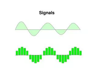
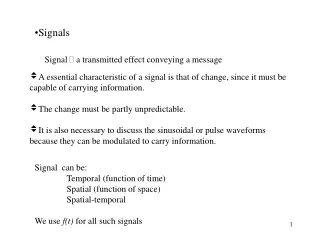
An ideal generator produces an induced emf that oscillates. Sine or cosine wave The oscillation is characterized by its period. The inverse of the period is the frequency. f = 1/T Cycles per sec, or Hz Angular frequency in radians 1 period = T Sinusoidal Signal e0 t
The amplitude of a sinusoidal signal is the peak value. Also maximum negative value The average value is zero. equally above and below zero The average value of the square is half the peak squared. Root mean square value Amplitude e0 t -e0 e02 0 t
The phase of a signal compares the time at a point to the time for the peak. Fraction of a period Phase is measured as an angle. Divided into 2p radians Compare to 360° Phase f = t/T e0 t
A phasor diagram maps the cosine onto the x-axis of a circle. x = e cos wt A vector represents a changing value like voltage. Magnitude for amplitude Angle for phase Moves counterclockwise with time Phasor e q e cos q
An AC source and resistor make a one-loop circuit. The resistor voltage must balance the source voltage. Lower case for AC The current follows from Ohm’s law. Oscillates as well AC Resistance v R
Power Loss • Power loss in an AC circuit depends on the instantaneous voltage and current. P 0 t
It’s more useful to look at the average power loss. Use RMS voltage or current. The form can reflect current, voltage or both. Average Power P 0 t next