Download
1 / 32
320 likes | 464 Vues
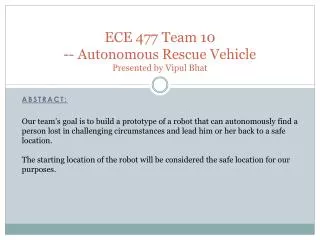
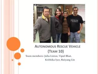
Autonomous Rescue Vehicle (Team 10) . Team members: Julia Liston, Vipul Bhat , Krithika Iyer , Ruiyang Lin. Project Overview. Our team’s goal is to build a prototype of a robot that can: Use GPS to locate a lost person Autonomously navigate towards the person

E N D
Autonomous Rescue Vehicle(Team 10) Team members: Julia Liston, VipulBhat, KrithikaIyer, Ruiyang Lin
Project Overview • Our team’s goal is to build a prototype of a robot that can: • Use GPS to locate a lost person • Autonomously navigate towards the person • Lead him or her back to a safe location, which is the starting location of the robot
PSSCs • An ability to move and steer using appropriate motors and drive systems • An ability to transmit GPS coordinates from the rescue-point transceiver to the robot via an RF module • An ability to receive and process GPS coordinates on the robot and move toward the given coordinates • An ability to detect obstacles and navigate around them using ultrasonic sensors. • An ability to monitor the battery level of the robot
Block Diagram (continued) Rescue-Point Transceiver +3.3 V Power Supply Module Microcontroller RF Transmitter Module (Xbee Pro) PWR _CTR GPS Module UART (9 bit)
Component Selection (Continued) • Microcontroller • 2 PWM • 2 UART • Minimum 4 ATD • Minimum 14 digital I/O pins • Fast to handle data input (At least 32-bit preferably, with CPU at least 50MHz) • 3.3 V operating voltage • Final choice: PIC32MX120F032B for Robot and for the rescue point transceiver.
Component Selection (Continued) • Motors • Enough torque to handle rugged terrain • Steady state current relatively low to reduce power • Built-in gear box to simplify design • Chose: Dagu 25D Motor with 34:1 Gearbox • GPS receiver • Accurate locating capability • Relatively inexpensive • Communicate through UART • Chose: ADH Technology - GPS-11571 • RF module • Long range communication (6 miles) • Conform to FCC requirements • Chose: Digi International Inc - XBP09-DPSIT-156
Component Selection (Continued) • Ultrasonic Sensors: • Easy to use • ATD • High Resolution • Cost-effective • Chose: Maxbotix LV-EZ4 • H Bridge • Delivers up to 5 A continuous • Low turn-on resistance • Built-in circuit protection • Chose: TLE5206
Packaging • Constraints • Traverse rugged terrain • Lightweight and Sturdy • Room for PCB and off chip peripherals • Minimize cost • Looks cool
Packaging (Continued) PCB GPS Batteries Ultrasonic Sensors
Packaging (Continued) Rescue-Point Transceiver
PCB Layout (Microcontroller) Robot Transceiver
PCB Layout (Transceiver Power Supply) 3.3 Volt Ground
PCB Layout (Robot Power Supply) 3.3 Volt
PCB Layout (Robot Power Supply) Digital Ground
PCB Layout (Robot Power Supply) 7.2Volt
PCB Layout (Robot Power Supply) Motor Ground
Preliminary Software Design • Completed testing: • Can transmit and receive with UART • ATD • PWM – Motor control • Timing modules and interrupts • Future design: • Motor control • Navigation algorithm – ultrasonic sensors • Process GPS data • Transmit and receive with RF module