Download
1 / 6
60 likes | 78 Vues
According to the conclusions, the problem of oil displacement fine air mixtures (hereinafter HCV) on the models of the reservoir at different gas content in the mixture (0% to 100%) and the effect of a mixture of structure displacement is not sufficiently explored and require research. The creation of an appropriate laboratory equipment is urgent to achieve these goals, allowing obtaining the fine study of HCV and its filtration through a porous medium, namely oil reservoir model.

E N D
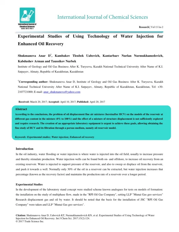
Experimental Studies of Using Technology of Water Injection for Enhanced Oil Recovery Shukmanova Anar D*, Kambakov Tleubek Uabovich, Kantarbaev Nurlan Nurmukhamedovich, Kabdushev Arman and Taussikov Nurbek Institute of Geology and Oil Gas Business After K. Turysova, Kazakh National Technical University After Name of K.I. Satpayev, Almaty, Republic of Kazakhstan, Kazakhstan *Corresponding author: Shukmanova Anar D,Institute of Geology and Oil Gas Business After K. Turysova, Kazakh National Technical University After Name of K.I. Satpayev, Almaty, Republic of Kazakhstan, Kazakhstan, Tel: +30- 2107721000;E-mail: anar_shukmanova@yahoo.com Received: March 20, 2017; Accepted: April 10, 2017; Published: April 20, 2017 Abstract According to the conclusions, the problem of oil displacement fine air mixtures (hereinafter HCV) on the models of the reservoir at different gas content in the mixture (0% to 100%) and the effect of a mixture of structure displacement is not sufficiently explored and require research. The creation of an appropriate laboratory equipment is urgent to achieve these goals, allowing obtaining the fine study of HCV and its filtration through a porous medium, namely oil reservoir model. Keywords: Experimental studies; Water injection; Enhanced oil recovery Introduction In the oil industry, water flooding or water injection is where water is injected into the oil field, usually to increase pressure and thereby stimulate production. Water injection wells can be found both on- and offshore, to increase oil recovery from an existing reservoir. Water is injected to support pressure of the reservoir, and also to sweep or displace oil from the reservoir, and push it towards a well. Normally only 30% of the oil in a reservoir can be extracted, but water injection increases that percentage (known as the recovery factor) and maintains the production rate of a reservoir over a longer period. Experimental Studies In the development of the laboratory stand concept were studied scheme known analogues for tests on models of formation: the installation on the study of multiphase flow, made in the "RPI Oil Gas Company", setting LLP "Munai Gas geo services" Research displacement gas and oil by water. It should be noted that the basis for the installation of JSC "RPI Oil Gas Company" were taken and LLP "Munai Gas geo services". Citation: Shukmanova Anar D, Uabovich KT, Nurmukhamedovich KN, et al. Experimental Studies of Using Technology of Water Injection for Enhanced Oil Recovery. Int J Chem Sci. 2017;15(2):124. © 2017 Trade Science Inc.
www.tsijournals.com | June-2017 Schematic diagram of the experimental stand we improved by introducing additional nodes for HCV (LLP Munai Gas geo services), i.e. blocks structure observation and measurement of amounts mixture fluid at the inlet and outlet of the installation. The air-gas mixture obtained on the stand via the jet device by injecting gas into the liquid flow. Preliminary calculations were performed with respect to the experimental conditions (work at low water and gas costs). As is known, the main geometric parameters of the jet device are working nozzle diameter, the diameter and length of the mixing chamber [1]. Diameter of the nozzle is calculated using the following formula: Q = ζϜ(2∆p/p)0.5 (1) Where, ζ-Coefficient of flow (for the diaphragm nozzle it is 0.615); F-flow area of the working nozzle; P-pressure difference; P-the density of the working fluid; Q-flow of working fluid. ∆p =pp-pпр (2) Where рр-the working pressure of the stream before entering the working nozzle; рир-the pressure in the receiving chamber of the jet device. The diameter of the mixing chamber was determined from the ratio dc/dKC=2. This relationship is taken for reasons of obtaining sufficient quantities of gas with a slight reduction of pressure on the jet device. The length of the mixing chamber is determined from the ratio of jet devices for pumped gas: (3) LKC = 30dKC The calculated parameters of working bodies of the jet device are shown in TABLE 1. TABLE 1. Parameters of the working bodies of the jet device. Parameter Performance 1 2 3 The diameter of the mixing chamber, mm 0.15 0.25 0.4 The length of the mixing chamber, mm 0.35 0.50 0.65 - - 10.5 13 Schematic diagram of the experimental apparatus is shown in FIG. 1.
www.tsijournals.com | June-2017 FIG. 1. Schematic diagram of the installation for the water-gas mixture filtration studies on the oil reservoir model. 1-Capacity; 2-Metering pump; 3-Compensator; 4,8,15,17,19; 4-Valve; 5-Balloon; 6- Reducer; 7,10,14; Gauge; 9-Jet apparatus; 11, 13-Camera with transparent insert; 12-Reservoir model; 16-Team capacity; 18-A flow meter; 20 -A measuring vessel The installation consists of the following units and assemblies. 1. Block of fine cooking HCV. It consists of a water supply node and receiving node gas and HCV. The water supply unit. The water supply carried out from the container 1 metering pump 2, equipped with a compensator 3. The water supply control can carry out in two ways: a change in the pump plunger stroke length and control valve 4. A pressure gauge measures the pressure in the water supply line. Gas supply assembly. Gas is supplied from cylinders 5. The model gas used as nitrogen-gas similar in their properties with methane and often used in the experiments. In addition, the use of nitrogen provides the required operational safety. The gas pressure at the outlet of the cylinders is regulated gear 6, which provides constant pressure of the gas entering the system. A manometer 7 model measures the pressure in the gas supply line. According to the relevant water and gas, lines enter the receiving node HCV, which is a jet device 9. The working stream is water, injected or the pumped-gas. A manometer measures the pressure at the outlet from the jet device. The gas pressure at the outlet of the cylinders is regulated gear 6, which provides constant pressure of the gas entering the system. According to the relevant water and gas, lines enter the receiving node HCV, which is a jet device 9. The working stream is water, injected or the pumped-gas. A pressure gauge measures the pressure at the outlet of the jet device [2]. Conducting laboratory experimental studies preceded the preparation of the model, which includes the preparation of sand and sand packing of the model and the determination of reservoir properties of the model and the creation of an initial water oil saturation. The studies conducted on samples of oil East Kumkol field. All experiments performed at 25° to 27°C. For packing model used purified from impurities, washed and dried sand fines (sand particles smaller than 100 microns, the predominant size of 30-40 microns) [3]. The model is a tube made of stainless steel and provided with covers with inlet fittings and filters. For models installed similarity conditions and the resulting quantitative similarity criteria to define the parameters of the experiments on the displacement of oil, such as the minimum length of a model for unconsolidated sands and weakly cemented sandstone, permeability is expressed in terms of area, the permissible length of the stabilized zone is 0.1 times the total length of the sample. The length of the model used in the experiments taken equal to 50 cm, which is higher than the calculated minimum allowable length of the model [4]. Interfacial tension at the border "water-Kerosene" measured by measuring device "Kruss K9" surface and interfacial tension. Methods of measurement are as follows. In one of the fluids (and heavier-water) immersed metal plate, then poured on top of the second fluid (lighter-kerosene) so that it is not mixed with the first. Then, the plate moves slowly from the bottom to the
www.tsijournals.com | June-2017 top fluid while fixed force occur, which prevents transfer of liquid from one plate to another. The device automatically detects the maximum value of this force, and converts it into a value of the surface tension [5]. Measured the interfacial tension at the border "water-kerosene" is σ=27,8 mN/m2. Kerosene viscosity is 1.5 mPa-s. Average permeability of the sand in the water is equal to 0.547 D parameter is 0.18 (according to the schedule). Model bulk core is a stainless-steel tube of 0.5 m length and 25 mm inner diameter, covered on both sides with connecting nipples lids. To prevent sand production from the model set under the covers filters consisting of two parts: a steel disk with holes and secured beneath the porous filter made of a mixture of fine sand and an epoxy resin. Driving the implementation of the technology of injection and HCV shown in FIG. 2. Experimental studies carried out as follows. Provided through 14 holes Products in the separator 15 separated into oil, gas and water. Oil on line 16 enters the pipeline; the gas is fed through line 18 to receive an inkjet device. In the case of a low- pressure gas outlet, 15 from the separator can be further squeezed gas blower 19. The amount of gas regulated by valve 8. Water supplied via line 17 to receiving booster pump 4 and then fed via line 9 to the ejector nozzle operating 1. At line 11 of pump 13 5 working capacity in water are added to the foaming surfactant. Resulting in the ejector 1 HCV is compressed to the required pressure pump 3 and via line 12 is pumped into the injection wells 2. Ejector pump and installation of the first stage-The jet compressor used as a blower 19 to increase the gas pressure to the intake of the jet device. In this case, water is fed from the separator 15 through line 17 for receiving the feed pump 23 and further to the gas-water separator 22, pump 21, from which it is fed into the ejector nozzle 20. The working gas enters the separator 15 to receive the ejector 20. The resulting pressurized HCV enters the gas-water separator 22, which separates the gas from water. Some gas under elevated pressure is to receive the main ejector 1 and water-to the pump 4, followed by a scheme similar to that of FIG. 2, operating in an ejector nozzle 1. FIG. 2. Scheme of the implementation of technology in the WAG oil fields. 1-Second stage ejector; 2-Injection well; 3,4-Pumps; 5-Container with a surfactant; 6, 7,8-gate; 9-water injection line; 10-gas line; 11-SAW supply line; 12-Line injection mixture; 13-metering pump; 14-inlet manifold; 15-three-phase separator; 16-
www.tsijournals.com | June-2017 nefteprovod; 17-water line; 18-gas pipeline; 19-pump-ejector unit of the first stage; 20-first-stage ejector; 21-power of the first stage ejector pump; 22-gas-water separator; 23-booster pump Part of the working fluid circulates in a closed loop pumping and ejecting plant in the first stage 19 and substantially heated. Therefore, there is hot water and pumped into the injection wells. Therefore, in the technological scheme of HBV it is possible not only to maintain reservoir pressure, but also to maintain the temperature of the reservoir, which is important for the development of viscous and highly paraffinic oils. HCV derived mainly horizontal ESP ejector compressed to a pressure of about 20 MPa, and injected into the injection wells. In the study was measured inlet pressure to the PBX model, RO output from the model, the volume of published models of kerosene and water, respectively, VKer and Vwater time measurements. Since the duration of the experiment is large enough (a few hours), the current measurement time is recorded in "hour: minute: second" format, and then re-calculated time difference in seconds [6]. The results of laboratory experiments were determined: 1. The coefficient of oil displacement (4) Where, Vker-Prepared from the volume model kerosene; Vmod-The volume of kerosene pumped into the model. The number of pore volumes pumped (5) Where Vwater-the volume of water obtained from the model; Vpvm-pore volume model, it can obtained by multiplying the volume of an empty void ratio model. Besides water displacement kerosene, kerosene displacement performed by experiments with a mixture of water and surfactants (hereinafter-surfactants) to be used for the preparation of water-gas mixture. It is necessary to highlight the growth of the total increase in displacement coefficient obtained by displacing kerosene and HCV by surfactant additives since the displacement ratio may increase at the expense of surfactant additives and due to displacement is not water, but a mixture of water and gas. As the surfactant used in the initial stage Oil-MJT at a concentration of 0.1% by volume [7]. Water model carried out on two models (per-No 3-displacement technical No water and VP-2-displacement of a mixture of water and a surfactant (Oil-MJl), wherein the surfactant concentration was 0.1% by volume) [8,9] (TABLES 2 and 3). TABLE 2. Reservoir properties of the test patterns. Permeability, L Nitrogen Porosity Initial quantity Kerosene model, cm3 water Model No ТВ-3 ВП-2 4,077 3,650 0,418 0,482 0.3314 0.3692 51 53 TABLE 3. Average values of the water and kerosene costs of the experiment, the duration of the displacement, number of pore volumes pumped and displacement ratios.
www.tsijournals.com | June-2017 Rate, cm3/с Model number Amount pumped Vnop Coefficient displacement Kerosene Water ТV-3 0.0016 0.0064 3.17 0.53 VB-2 0.00074 0.0086 3.28 0.60 Conclusion The analysis of experimental trials of the technology variable water injection and gas, allowing obtaining a finely dispersed water-gas mixture and studding its filtration in porous media on the core samples of East Kumkol field. Developed a schematic diagram of the experimental stand for research of oil displacement by water-gas mixture. The model, produced by modeling of oil displacement by water-gas mixture. Developed and obtained results of experimental studies of variable water injection technology and a mixture of water and surfactant. Thus, the addition of 0.1% Oil-MJ1 increases the displacement efficiency of 15% to 20%. REFERENCES 1.Bugulma A. Application of water-gas-based gas systems to increase oil recovery. Avtorferat dis. 2002;pp:25. 2.Ivanivshin VS, Karnaushevskaya L, Liskevich EI. The effectiveness of the creation of gas-repression on Bitkovskom fields. Oil Industry. 1975;pp:35-8. 3.Egorov Y. Development of technologies WAG using a pump-ejector systems for enhanced oil recovery. Abstract, dis. Moscow, 2006;pp:24. 4.The Method of water-gas stimulation. Russian patent. 2190760. 2002. 5.Lysenko VD. Calculation of the development of oil deposits at a gas waterflood. Petrol Eng. 2003;6-11. 6.Laman BFL. Hydro pumps and installation. Engineering. 1988;pp:256. 7.Piyakov GN, Yakovlev AP, Kudashev RI, et al. Experimental studies WAG. Oil hozyaystvo.1991;829-30. 8.Cook IA, Kovalev AG, Kudinov VI, et al. Intensification of oil production from oil reservoirs flooded by alternately injecting water and gas. Oil hozyaystvo. 1973;12:25-8. 9.Mikhailov DN, Stepanova GS. Mechanism of displacement of oil and gas and water in the presence of foaming surfactants. Proceedings of Natural Sciences Ser. Technol oil gas. 2004;5:50-60.