Download

1 / 21
210 likes | 225 Vues
Minutes 9 22 2015 meeting. A Fedotov, K Hamdi, D Kayran, L Snydstrup, K Smith, J Tuozzolo, A Zaltsman Transport Beam Line Design development of beam line will be from the Booster to the 2nd 20 degree dipole.

E N D
Minutes 9 22 2015 meeting A Fedotov, K Hamdi, D Kayran, L Snydstrup, K Smith, J Tuozzolo, A Zaltsman Transport Beam Line Design development of beam line will be from the Booster to the 2nd 20 degree dipole. There are 2 diagnostic lines shown branched toward the inside of the ring. They will not fit this way because the tunnel wall interferes and must be flipped toward the inside of the RHIC ring (toward the triplet). The transport line is 2.38 inch inside diameter, larger than ERL (approximated 2.0 inch). Discussion on diagnostic line: Is a separate beam line with a high power beam dump needed or is the macro bunch train short enough that heating into the faraday cups and YAG screens is not a problem. RF Cavities Design Current beam line configuration has the following RF cavities: SCRF Booster Cavity (from ERL), 2.1 GHz Cavity (new procurement), 9 MHz (from RHIC), and 704 MHz Cavity (new procurement). A deflection cavity is now shown in the second diagnostic stub line after the 20 magnet. This cavity is used to characterize longitudinal phase space to be used for 2.1 or 704 cavity tuning. The warm 9 MHz cavity is an existing device – the RHIC “bouncer” cavities. A. Zaltsman cites power at 3 kW; A. Fedotov said the required power has been estimated at 6 kW, but the beam loading needs to be determined and the power may be less. Drawings for 2.1 GHz are completed (also Spec and SOW). We should be ready to go out for bidding in about 3 weeks. K. Smith to call a meeting to start discussion of the RF design of the transport section, the deflection cavity, and the diagnostic lines. Solenoid magnets: 1000 Gauss Merger solenoids, 535 Gauss Matching solenoids. These solenoids are designed for 2.5” pipe. They have Ri=5.08cm, Ro=16.84cm. The Merger Sol. is 14.8cm long; the Matching Sol. length is incorrectly shown at 14.8 (should be about 11cm). Should just the high field solenoid be purchased? Its field requirement is 2x the low field; it may be cost effective to purchase just one magnet type. Same thought for power supply. Should the horizontal and vertical corrector be integrated into the solenoid design. Field requirement is 100 g/cm; Wuzheng is analyzing. Other magnets: Transport line shows 3 quadrupoles (in Phase II), In Phase II two solenoids are replaced by Zig-Zags (and associated dipoles). Correctors at DC eGun: There is a Cornell designed dipole corrector at the Cathode position (air side) and a corrector inside the first solenoid, also designed by Cornell. Maybe this corrector can be integrated into the solenoid design. Diagnostics: May need more profile monitors in the transport line. ERL PM may be used; but, the aperture is different. BPMs: the vacuum chambers must be custom made to match the 2.38 aperture – buttons from ERL may be used.
Beam Transport and Merger Lines Phase 1
Overall Layout LEReC-I (1.6-2MeV): Gun to dump SRF gun used as a booster cavity
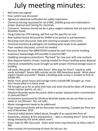
Diagnostics Gun to Booster Cavity ™ • Beam pipe size shall match ERL devices • Bake-out to 200C only?? • DC Gun instrumentation : • Large Button or ERL Button BPM(s) or Striplines?? • Profile Monitor in Laser Cross • Cathode Camera in Laser Cross • Dual Solenoids & BPMs Injection BPM = 6 YAG = 2 ICT = 1 DCCT = 1 Emittance Slit = 1 Halo Pairs = 2 Faraday Cup = 4 Cathode Camera YAG BPM BPM BPM BPM BPM 5-Cell 704 MHz SRF Cavity Solenoid(s) YAG BPM Quadrupole(s) DC Gun (Photocathode) DCCT 704 MHz SRF Booster Em-Slit Vertical & Horizontal Halo Monitors ICT 2.1 GHz Warm Cavity Laser Injection Port
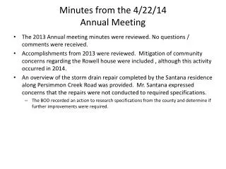
Diagnostics - Beam Transport ™ • DETAILS: • 1st Diag. B/L for commissioning • Do we need to add YAG in transport? • REVISED LAYOUT BELOW – Per Jorg’s model • Do we need more emittance measurements in transport? Could add Quad + PM… -> not in baseline and money is too tight YAG 5-Cell 704 MHz SRF Cavity BPM BPM BPM BPM BPM Faraday Cup BPM BPM BPM BPM 704 MHz Warm Cavity Vertical Halo Monitor Quadrupole(s) 3 locations Solenoid(s) 8 locations 2.1 GHz Warm Cavity e-Beam Transport BPM = 9 YAG = 1 Faraday Cup = 1 + 2 Halo Scraper Pair = 1
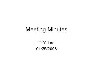
Merger & Diagnostic Beam Lines™ • DETAILS: • Drift length for RF deflecting cavity not know. • Need electrostatic kicker and beam dump parameters for diagnostic line. • Waiting on information from the Cornell RF deflecting cavity design. Flying Wire BPM To Cooling Section Au Ion Beam Yellow Ring YAG BPM Dual YAG Drift Length not known YAG Faraday Cup e-Beam Transport BPM = 2 YAG = 4 Faraday Cup = 1 Flying Wire = 1 Deflecting Cavity Electrostatic Deflector
20o Dipole Merger Section See slide #2 YELLOW RHIC Beam BLUE RHIC Beam TRANSPORT SOLENOID ERL, Profile Monitor ID=1.87” Cornell, Wire Scanner OD=1.50” ; ID=1.38’’ HIGH FIELD SOLENOID BPM PROFILE MONITOR EMITTANCE SLIT Quad/SQ CORRECTOR BPM w/ ERL Buttons ID=2.37” YELLOW RHIC Beam BLUE RHIC Beam PROFILE MONITOR 20° DIPOLE kh
Profile Monitors ERL PM With Ferrite only ERL PM With Ferrite & contact point 25x15mm YAG Mod needed for larger YAG ? Mod needed for larger YAG 25x15mm YAG 40mm YAG • Cooling Section PMs • Vacuum chamber modified • Enlarged 1.75” optics port penetration to 2.37” for illumination & ease of fabrication. • Simulation shows acceptable results. • 100μm YAG current choice • Ferrite temp rise due to 19mW => 2.2°C (low enough to disregard) • 20cm Radius of Mu Metal puts optics assembly ~20cm away from YAG crystal • Transport ERL PMs • Beam size (4mm sigma) in TWO transport PMs too large for 25x15mm YAG • require redesign of YAG & holder for TWO PM’s • Location of 25x15mm YAG PMs needs to be determined • All in transport (2 with modified – larger – YAG crystals) • Need beam size simulation in energy spectrometer beam line • Cage in all 5 ERL PMs will require modification • Addition of ferrite rings • May require single contact point in vacuum … moves to energy meas. B/L
Profile Monitors ERL Profile Monitor from Radiabeam Cooling Section Profile Monitor Stage Assembly (Linear Feedthrough) Zero Length adapter flange Profile Monitor YAG Screen Assy.
Impedance matching Need 180 deg chamber & rest of Transport line Estimate of the wake amplitude superposition of the 30 electron bunches using the one-bunch simulation shown on the previous slide. The oscillation amplitude decay is approximated by and exponential. The contributions from individual bunches added in quadrature are elements of a geometric series.
BPMs in Transport Section Small Dia. BPM Housings (2.38 ID), 10mm buttons ERL Buttons different size and shape
Cooling Section Emittance Slits • Requisition for commercial vacuum linear stage. • Fabrication drawings complete and approved. • Central Shops requisition approved for vacuum chamber and W slit. • The slit needs to be grounded at the vacuum chamber when scanning. • Delivery dates: shifter, vacuum chamber, W slit, mounting hardware.
Vacuum Hardware Standard beam tube: 2.5 OD x 2.375 ID 304L Stainless Steel Beam line bellows 2.38 shielded design. VAT RF shielded valves. RF Shielded gauge and pump cross.
20o Dipole Magnet Requisition approved SOW – 2 magnets by 10/1/2015. Order Placed 5/6/2015 Everson Tesla Estimated Delivery 1st two magnets 10/1/2015 Distance Between Pole Faces = 10.4 cm (4.1 in.) Magnet Vertical Gap = 10 cm Vacuum Chamber V Aperture = 9.5 cm (3.74 in.)
Transport Line Matching Solenoid Transport Solenoid (preliminary) ----- to be mounted on 2.5” pipe (Copper winding starts at R=2”) 1.27 cm (thickness) By using #5 square wire Io = 17.77 A N = 720 (60 turns along Z-axis; 12 layers along R) Total 12792.7 A-turn Bo = 535.4 G Bz** integral = 7.27E6 G2-cm Effective Lm = 29.5 cm 14.8 Overall J =-73.501 (A/cm2) R [cm] 5.08 16.84
Transport Line Merging Solenoid Merging Solenoid (preliminary) ----- to be mounted on 2.5” pipe (Copper winding starts at R=2”) 1.27 cm (thickness) 14.8 By using #5 square wire Io = 18.13 A N = 1140 (60 turns along Z-axis; 24 layers along R) Total 26112 A-turn Bo = 1088.39 G Bz** integral = 3.06E7 G2-cm Effective Lm = 30.14 cm J = -75 A/cm2 (Overall) 5.08 16.84 R [cm]
LEReC Cooling Section Design Room LF & HF solenoid and 20o dipole magnets fabrication drawings(KH) Beam Diagnostics: BPM chamber and buttons (VDM) Beam Line 5” bellows with shields fabrication drawings (GW) 20o dipole vacuum chamber for impedence review (KH) 180o dipole fabrication drawings (KH) Spectrometer magnet (180o dipole) revisions (KH) 180o vacuum chamber + large sliding bellows fabrication drawing (KH) Beam Diagnostics ES W slit & chamber fabrication drawings (VDM) 20o dipole vacuum chamber fabrication drawings (KH) Cable tray and penetration drawings and excel sheet (AF) Beam Diagnostics: PM vacuum chamber fabrication drawings (GW) Beam Diagnostics: standard PM fabrication drawings (GW) Beam Diagnostics: special “hybrid” ES/PM/BPM fabrication drawings (GW) Beam line solenoid/BPM stands & vacuum chamber stand (VDM) 20o magnet stand drawing (KH) 180o magnet w/hybrid BPM stand drawings (KH) on hold Magnetic shielding drawing and solenoid magnetic measurement test station (VDM) In tunnel, magnetic measurement “mole” for stray field studies HF dipole, quadrupole, and skew quadrupole corrector drawings
LEReC Design Room Source Design Work DC Gun Vacuum Chamber Fabrication Drawings (JH) DC Gun SF6 Pressure chamber specification control drawings (JH) DC Gun cathode cooling design for Karl S. Cornell (JH) DC Gun stands (JH) DC Gun to Booster SRF booster cavity beam line (JH) DC Gun cathode insertion drive (WJ/VDM) DC Gun cathode coating system vacuum chamber (PC) DC Gun cathode transfer load lock and vacuum chamber (WJ) Cathode production coating system design (BM)
LEReC Design Room Other Work RHIC 1:00 move real estate drawings (V.DM.) Phase 2: 5 cell cavity positioning (RM) – Revised Position on hold Phase 1 cryogenic system layout (RM) 2.1 GHz warm cavity fabrication drawings (MG) 704 MHz warm cavity fabrication drawings (SP) Transport & Merger line layout (RM) Locate booster cavity, solenoids, BPM’s, RF Cavities, PM’s, Diagnostic Lines Transport & Merger Line Solenoids Transport & Merger Line Correctors Transport & Merger Line BPM’s Transport & Merger Line Profile Monitors Merger Line Flying Wire Diagnostic Beam Lines and Components Kickers, RF cavity, beam dump,