Iterative Algorithms for Low Power VLSI Placement
This presentation explores low power design techniques essential for modern portable electronic devices, focusing on VLSI placement optimization. It emphasizes the critical role of managing switching activity to reduce power consumption. Various design levels are discussed, including architectural to physical, outlining tasks and methodologies for achieving low power dissipation. The research engages in innovative approaches such as transistor sizing, gate input ordering, and software optimizations. Aimed at improving energy efficiency without compromising performance, this work showcases iterative algorithms for enhancing standard-cell layout design.

Iterative Algorithms for Low Power VLSI Placement
E N D
Presentation Transcript
Iterative Algorithms for Low Power VLSI Placement Sadiq M. Sait, Ph.D sadiq@kfupm.edu.sa Department of Computer Engineering King Fahd University of Petroleum and Minerals Dhahran, Saudi Arabia Special Talk for KFUPM Funded Research Project
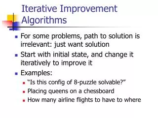
Plan of Presentation • Motivation • Some overview of low power design approaches • Objectives of research • Tasks, management, utilization, etc. • Conclusion
Motivation • Present day electronic portable systems such as Laptops, Palmtops, and other communication devices (Mobile Phones) require low power consumption. • Simple changes in design can result in considerable cost in power and or increased performance
Main Cause • Switching activity in the circuit (90% of total power dissipated is due to this) • In CMOS it is a function of clocking frequency, supplyvoltage, and capacitances (interconnect and gate input capacitances) • Power reduction can be addressed at • System Level • Chip (Processor/ASICs/etc) architecture design level • layout level
Levels of Design • During DA, power reduction can be addressed at • Architectural level • Logical Level • Physical Design Level • Partitioning • Floorplanning • Placement • Routing, etc.
Layers of Abstraction Levels of abstraction and corresponding design steps
Low Power • Looking at a large system, a laptop for example, power is consumed by the display, drives, CPU, etc • Addressing power only for one of these components is not sufficient • Statistically, the CPU may not be the main consumer of power (consumption depends on how the machine is used) • Again, in CPU, there are several other sub-components, and each of them consumes different percentages of powers • For example, optimizing the power of multiplier may not produce much reduction, since the multiplier may consume only a small percentage of total power
Approaches for Low Power • At all levels, information about switching activity is used, this include complex gate design, transistor sizing, etc • Transistor sizing (Decrease in transistor size results in decrease of power and increase of delay. Given a delay constraint, appropriate sizing of transistors that minimizes power dissipation can be found) • Other proposed methods • Ordering of gate inputs • Using multiple supply voltages (normal supply for timing critical paths, and reduced supply voltage for non-critical paths) • Technology independent optimization using Kernel extraction methods (not only to reduce literal count) but also to reduce switching activity
Data Path • Switching activity in datapaths can be reduced by sending values which are true or complemented (whichever results in less switching), with an additional line asserted when complemented values are sent • Also during datapath synthesis, scheduling and allocation in HLS, power can be optimized
Minimization at Logic Level • Low Power Sequential Circuits: • Assigning codes for high transiting states in such a way that the distance between them is small • Logic introduced must not result in excessive transitions at combinational gates • Gray encoding (counters that count in Gray code) • One hot encoding
Retiming • When flip-flops in synchronous sequential circuits are repositioned to minimize clock period • It was observed that the switching activity at flip-flop outputs is significantly less than the activity at the flip-flops inputs. (This is mainly because of spurious transitions at the inputs that are filtered out by the clock) • This observation can be exploited in a retiming technique to reduce power • Spurious transitions can also be reduced by making equal the delays of all paths that converge at each gate. (10%-40% of dissipation can be due to spurious transitions)
Power off • In most circuits values of memory/registers need not be updated in every clock, (simple circuitry can be used to inactivate these registers) • Same techniques can be used in register files (switching-off memory sub-systems, also memory interleaving, caching both op-code, operands and results, etc) • Further, sub-circuits on chips can be powered off, e.g., when branch condition is executed by the CPU, the multiplier can be powered off
Software • It is the software that runs and burns the power • Compiling code for power optimization have been reported and used • Transforms have been proposed that will reduce accesses to main memory, efficient utilization of caches, etc • Power management using SW is another issue
Low Power in Physical Design • Physical design comprises of phases such as Partitioning, Floorplanning, Placement, Routing, etc • In this work we target cell Placement • Standard Cell Design methodology is adopted • Performance is also considered, since performance can never be compromised while reducing power
Algorithms for Low Power PD • All modern iterative algorithms will be used and experimented (GAs have been earlier used) • Genetic Algorithms (Operators, Encoding, etc) • Simulated/Stochastic Evolution (Goodness functions) • Simulated Annealing • Tabu Search (Parameters, neighborhood strategies, etc) • Hybrids and Meta-heuristics (Open topic) • We hope to develop and implement iterative algorithms for VLSI standard cell placement with the objective of reducing • Area, Power, Delay (improving performance)
Cost Computation • Due to multi-objective nature of this NP hard problem fuzzy logic (fuzzy goal based computation) will be employed in modeling the cost function • Fuzzy logic can also be used in other steps of the algorithms (choice of parameters, • Membership functions will be defined and operators such as OWA (due to Yager) etc., will be used • Cost function?
Expression for Power in CMOS Ptotal = iV pi(Ci VDD2 fclk) Ci =jFiCjg + Cijr Where pi …… is the switching probability of gate i. Ci …… is the capacitive load of gate i. Cjg…… is the input capacitance of gate j. Cijr…… is the interconnect capacitance between i and j. fclk…… is the clock frequency. Vdd……is the supply voltage. Fi …… is the set of fanout gates of gate i.
Delay of a Path T= i=1k-1 (CDvi + IDvi); IDvi = LFvi Cvi SLACK = LRAT - T Where T…… is the delay of path “”. {v1,v2…, vk}… is the set of nets belonging to path . CDvi……is the switching delay of cell ci driving net vi. IDvi……is the interconnect delay of net vi. LFvi ……is the load factor of the driving cell ci. Cv i…… is the capacitive load of the driving cell ci. LRAT… is the latest required arrival time. SLACK…is an indicator of long path problem.
Membership Functions Membership function within acceptable range. By lowering the goal gi to g*i the preference for objective “i” has been increased
Membership value of a Solution IFa solution is within power goal AND within circuit delay goal AND within area goal THENit is an acceptable solution (x) = min(A(x), D(x), P(x) ) + (1- ) (1/3) i=A,D,Pi(x) Where (x) … ……… is the membership value of solution “x”, in fuzzy set acceptable solution. i(x) (i=A, D, P) … are the membership values of solution “x”, in fuzzy sets within low power goal, within low delay goal and within small area goal.
Tools/Technologies/Benchmarks • Tools used will include timing analyzers (for critical path generation, must be developed) and software for generating switching probabilities • ISCAS Benchmark circuits will be used for comparison of results of various heuristics • 0.25/0.18 Micron technology will be used in design (Cell library has been obtained from MOSIS • The final product will be integrated with existing DA system (OASIS)
Project Tasks • Collection of data and tools (Design/Implementation?) • Further literature review • Encoding schemes for the various iterative algorithms • Experimentation with neighborhood strategies • Fuzzification of heuristics (cost, parameters, size of neighborhood, etc) • Implementation of proposed heuristics, experimentation, comparison, tuning, etc • Documentation and reporting
Management and Schedule • The Project Team comprises three investigators • Support for GA/RAs • Duration, two years • Budget, less than US$ 40,000/-
Conclusion • Engineer a number of general iterative heuristics for multi-objective (power and performance) placement • Seek appropriate means of expressing and manipulating design information using fuzzy logic, and rely on fuzzy decision making during the search • Implement (heuristics and their hybrids) and integrate with existing DA system