Download
1 / 10
100 likes | 225 Vues
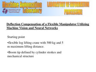
LABORATORY OF INFORMATION PROCESSING. Machine Automation. Laboratory. Lappeenranta University of Technology. Deflection Compensation of a Flexible Manipulator Utilizing Machine Vision and Neural Networks. Starting point

E N D
LABORATORY OF INFORMATION PROCESSING Machine Automation Laboratory Lappeenranta University of Technology Deflection Compensation of a Flexible Manipulator Utilizing Machine Vision and Neural Networks • Starting point • flexible log lifting crane with 500 kg and 5 m maximum lifting distance. • Boom tip defined by cylinder strokes and mechanical structure
LABORATORY OF INFORMATION PROCESSING Machine Automation Laboratory Lappeenranta University of Technology • User interface converts global coordinates to cylinder strokes • ease of positioning • necessitates solving of inverse kinematics of manipulator • Solving inverse kinematics • link matrices and flexibility matrices produced no applicable results • solution based on geometry is rigid
LABORATORY OF INFORMATION PROCESSING Machine Automation Laboratory Lappeenranta University of Technology • Inverse kinematic model is integrated into the control system • invisible to the user • fast, control running at 1 kHz Inverse kinematic
LABORATORY OF INFORMATION PROCESSING Machine Automation Laboratory Lappeenranta University of Technology • Position deviations due to • boom flexibility • joint wear • imprecise transducer offset • inaccurate boom geometry • low amplicification of PD-controller • Together with high amplification of mechanical structure max deflextion 40 mm. Deflections before compensation O is set point value X is real value obtained with camera
LABORATORY OF INFORMATION PROCESSING Machine Automation Laboratory Lappeenranta University of Technology Deviation correction possible with function fitting. Problem: hard to automate Solution: Automation of function fitting possible with neural networks Problem: lack of teach data Solution: Automation of data collecting with machine vision and measuring cycle.
LABORATORY OF INFORMATION PROCESSING Machine Automation Laboratory Lappeenranta University of Technology • Machine vision system • Sony DXC-9100P-videocamera • Pentium II PC • Matrox Meteor II-grabber • Matrox Imaging Library + ANSI C • Matlab-dSpace Interface Library (for communication with DSP-card)
LABORATORY OF INFORMATION PROCESSING Machine Automation Laboratory Lappeenranta University of Technology Machine vision and measuring cycle communication protocol Control system Machine vision system Set point value • Positioning of boom tip • stroke deviation 0.3 mm Obtain real coordinates Next step
LABORATORY OF INFORMATION PROCESSING Machine Automation Laboratory Lappeenranta University of Technology Obtaining coordinates with machine vision Red filtering of picture • Form blobs • calculate weight centers If more than one red point -> abort Blue filtering of picture • Form blobs • calculate weight centers Phase 1. Projecting picture to plate field coordinates Find closest blue blob to red blob Note! Camera rotates between 0-90 Find closest blue blob to found blue blob Calculate picture window angle from blue blobs and transform picture to plate field coordinate system. Phase 2. Projecting picture to global coordinates Define camera placement • From control system • Set point value (global coordinates) • Predifined data • Calibration point value (global coordinates) Real value in global coordinates
LABORATORY OF INFORMATION PROCESSING Machine Automation Laboratory Lappeenranta University of Technology Teach process • Obtained data • set point value • cylinder stroke • obtained real value • cylinder stroke calculated from real value Feed-forward backpropagation multilayer neural network Cylinder stroke deviations at given point
LABORATORY OF INFORMATION PROCESSING Machine Automation Laboratory Lappeenranta University of Technology Results Deflectionsafter compensation Compensation Note! No decline in control speed